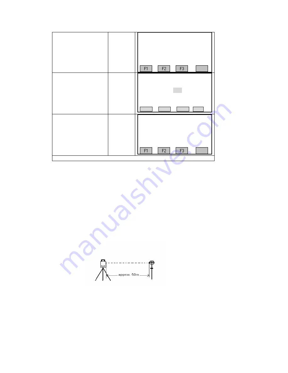
10.10 PARALLEL BETWEEN LINE OF SIGHT AND EMITTING
PHOTOELETRIC AXIS
·
Inspection
1.
Set the reflector 50m from the
instrument.
2.
Sight the center of the
reflector prism with reticle.
3.
Turn on and enter Distance
easurement Mode. Press [MEAS] to measure.
te the Horizontal Tangent Screw and Vertical Tangent Screw, to do electric collimation and
make the light route of EDM unblocked.
the bight zone find the center of emitting
.
4. C
k the center of reticle to coincide with the center of emitting photoelectric axis. If so, the
instrument is up to grade.
①
Press[Turn page] key to the
second page of the
Adjustment function.
※
1)
[F4]
Adjustment
F1 Inst. Constant (5)
F2 Tilt Parameter (6)
F3 State (7)
【
】
▲
Select
②
[F1] into Instrument
Constant Setting interface.
Input instruction constant.
[F1]
【
Inst. Constant Set
】
Inst Cons
:
0.0 mm
SAVE
Press
③
[F4] to conserve the
ng
Input
Instrument
stant
[F4]
【
Adjustment
】
▲
F1 Inst. Constant (5)
F2 Tilt Parameter (6)
F3 State (7)
setti and return to
Adjustment screen.
Con
+
※
1)F2
:
Auto compensation parameter is used for fac y setting. Please do not modify it.
tor
M
Rota
In
photoelectric axis
hec
191
Содержание STS-750
Страница 6: ...6...


