background image

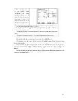
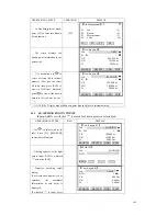
After finishing adding a 

known point, the program 

automatically add 1 (+1) to the 

tID, and continues to input 


Input Known Pt


                                  SANDING 

P

other know points, as shown in 

the right graph. 

To quit this program, press 

[ESC] to return to last menu.   


Job


Pt  ID

                                            1 

0.000 m 

Y/E   

              100.000 m 

X/N   

              100.000 

H         

              10


View                                          SAVE 

6.2.3   EDITING THE KNOWN POINTS 

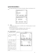
    This function allows editing known points in internal memory. 

OPERATIONAL STEPS 

OPERATION

DISPLAY 


View Known Pt


Job

                                            DATA 


Pt  ID

                                            1   


Y/E   

              100.000 m 

X/N   

              100.000 m 

H         

                              90.000 m 


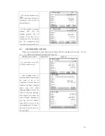
Use

 to select the job  

which contains the point to be 

edited. Press [ENT] to move to 

PtID item. 

SEARCH   D

ADD   EDIT 

ELETE   


Press navigation key


(or use search function) to find 

out the data needed to edit. 


View Known Pt


Job

                                    SANDING 


Pt  ID

                                            10     

.000 m 

 116.000 m 

Y/E   

               110.000 

 102

X/N   


H         


SEARCH   DELETE   ADD   EDIT 

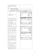
Press [F4] ([EDIT]) to start 

data editing function, and the

screen displays this point data.

Input new PtID, coordinate, and 


press [ENT] to move to the

next line. For  those  data

needed no edit, press [ENT]


ly. 


Edit Known Pt


Pt  ID 


direct


10     

00 m 

X/N   

                  102.000 m 

   116.000 m 


Y/E   

                  110.0

H         


Back                                                SAVE   

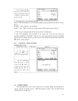
As input is finished, press

[F4] to save the edited data. 

The screen dis


plays as the right 

graph. Press [F4] ([OK]) to 

store the edited data. 

To re-edit this point please  

press [F1] ([CANCEL]). 


Input Known Pt


      Pt. Exist !    Want to cover the data ?   


DELETE                     OK 


167

Содержание STS-750

Страница 1: ...1 1 NOMENCLATURE take STS 750 for example Collimator Objective Lens Display Leveling Screw Adjustment Screw for Circular Vial Vertical Clamp Screw Vertical Tangent Screw Battery SB 21 Battery Locking...

Страница 2: ...Telesc Focusing Knob ope Instrument Center Mark Telescope Focusing Knob Eyepiece Circular Vial Te scope Grip le Horizo Tangent Sc ntal rew Base Horizontal Clamp Screw Tribrach Lock 2...

Страница 3: ...The chart above is the display screen there may be a little difference on local EY BOARD 1 2 3 4 3 5 It takes STS 750 for example here STS 720 has not Numeric key 1 Current operation section availabl...

Страница 4: ...information and data t In the m many choices there is shortcut figure viewed at the right of every ce PAGE there are several pages in one dialog box it can be used to page lay to next step 1 5M E rem...

Страница 5: ...or display To return to Soft Key of the first page To continue to Soft Key of the next page ENT To set screen information or display and return to the previous display 1 7 SYMBOL Symbol representes a...

Страница 6: ...6...

Страница 7: ...ge to view the next page Menu tree may be different in the order of display MUNE P1 Program Surveying Stakeout Free Station COGO Tie Distance Area plan Remote Height Reference Line Arc Roads Construct...

Страница 8: ...list lnst Constant Tilt Parameter State Comm Parameters Baud Rate Data Bits Parity End Mark Stop Bit Data Transfer Data Send Job Data Format System Information Battery Date Time Version Type Number 1...

Страница 9: ...bob 1 Setting up the tripod First extend the extension legs to suitable length make the tripod head parellel to the ground and tighten the screws Make the centre of the tripod and the occupied point...

Страница 10: ...the instrument 90 100g around its vertical axis and turn the remaining leveling screw or leveling C to center the bubble once more Repeat the steps for each 90 100g rotation of the instrument and che...

Страница 11: ...3 Adjust length of three legs of tripod make the circul middle se plate vial to level th ely otate the instrument horizontally by l parallel to the line connecting leve he plate vial by turning the le...

Страница 12: ...CTOR PRISMS measuring distance a refl r m needs to be placed at the target place Reflector stems come with single prism and triple prisms which can be mounted with tribrach onto a tripod or mounted on...

Страница 13: ...d adjust the eyepiece tube carefully erefore can input fig and haracter directly And since STS 720 is not equiped with numeric keypad it needs to press ENT navigation key slot Turn the locking knob ab...

Страница 14: ...several times such as A B C 7 keypad if it is F4 ST press ENT or navigation key to switch between character and figure inputting mode S 720 STS 720 series Total Station instrument needs to to start i...

Страница 15: ...press key once For STS 720 after starting character fig inputting mode press the first soft key and then the soft key corresponding to In editing mode the location of decimal point can not be changed...

Страница 16: ...ursor automatically moves to the next position press 7 twice showing B then press 8 three times showing F finally press 8 four times to show 8 So as to finish inputting 123ABF8 Input A B F 8 Measure 1...

Страница 17: ...ut fig 6 2 put 6 Measure 1 4 Pt ID 6 F F In 5 1 500 m RHT HZ 00 00 0 V 90 00 00 m m AB The soft key returnes to last age Pt ID 56 p Measure 1 4 RHT 0 m 1 5 0 00 00 HZ 0 90 00 00 V m m AB Press F2 and...

Страница 18: ...RHT 1 500 m HZ 0 00 00 V 90 00 00 m m AB Press F3 to input F So the pointID 568AF has been Input F Measure 1 4 Pt ID input 568AF 1 500 m RHT HZ 0 00 00 V 90 00 00 m m AB 11 Press ENT to end inputting...

Страница 19: ...0 00 00 V 90 00 00 m m Set Hz TILT BEEP 1 About the way to input character please refer racter to 2 7 1 inputting cha 2 7 3 DELETING CHARAC Input characters can be deleted only take STS 750 as OPERATI...

Страница 20: ...character on the right of A in the fig inputting statu insert 0 F1 Or Measure 1 4 Pt ID SAN DING RHT 1 500 m HZ 0 00 00 V 90 00 00 m m AB INSERT DELETE CLEAR NUMBER The cursor stays at the the N inser...

Страница 21: ...rogram press Surveying and fun after entering measure ction press Setting Station Input pointID Here take A12 as an example and press EN D T Then press F1 FIN to s Input Station PtID Set Stn Input poi...

Страница 22: ...b you ther diff job c selected job Press F3 JOB key to enter this function Pt Search JOB ANDG Pt ID Pt coord Select job input FIND 0 SET ENH Press navigation key moving cursor to job item through to s...

Страница 23: ...ts in those conditions such as not kn p ssel m A Find out all the point 1 Find out all the point A 1 Find out all the p s b A e g A8 A71 ABDE s with i PER ample ATIONAL STEPS taking as an ex In Progra...

Страница 24: ...er the MEASUR ill survey the distance of target light path nce trig E HOT KEY key the instrument w in In distance surveying if p aving branches of tree are in the ght path partial beam of light lead t...

Страница 25: ...et it would be kept even if t llustration prism constant 30mm OPERATION DISPLAY 2 2 Setting the Prism Consta Since n isms m red by different companie orresponding prism constant m he machine is turned...

Страница 26: ...fferentia H S sin cos S If the correction of atmosphere refraction and the earth curvature is neglected the c re D S cos The Vertical Angle Calculated From Horizontal Distance modulus of this instrume...

Страница 27: ...or atmospheric ing unit m hPa t a constant it varies with the chan perature and pressure of atmo e the atmospheric correction val The atmospheric correction The calculating formula f eter sph ument c...

Страница 28: ...ss F4 to save and return to the previous menu here press F3 SET again to save the setting and return to measure function F F4 3 EDM Settings EDM Mode Tracking Prism 30 0mm ATMOS GRID SET 1The inputing...

Страница 29: ...ENT Input Ht a MSL ENT Grid Factor on the screen input Scale and Ht a MSL and press ENT key The procedure wil SET 1 Scale 1 000000 S m 0 Ht a M L 0 0 Grid 1 00000 BACK 0 SET SET Press F4 SET to save t...

Страница 30: ...o return to EDM setting menu F1 DM Mo Tracking EDM Settings E de 30 0mm Prism ATMOS GRID SET 1 IR infrared distance measurement distance surveyed by the prism 3 2 6 Setting Multiply Constant This func...

Страница 31: ...ti b 1 Setting Horizontal Circle OPERATIONAL STEPS OPERA DISPLAY Collimate to the target point used for orientation setting Collimate to the target point Measure 1 4 Pt ID A1 RHT 1 500 m HZ 50 20 00 V...

Страница 32: ...input the needed angle and press ENT e g input 120 20 30 1 3 C If w zero press F1 0SET Screen shows as the right picture and presents whether to set horiz angle to zero If yes press F4 functi F1 CANCE...

Страница 33: ...lly c nverts and displays the prism point Co oint OPERATION ON Press F4 turn to the seco and instrument height Measure 1 4 Pt ID A1 500 m RHT 1 00 00 F4 HZ 0 nd page of soft key press F1 SetStn to set...

Страница 34: ...pointID will be automatically added 1 through the procedure ollimate to the prism center to c repeat the step and start surveying the next point 1 Measure 1 4 Pt ID A2 RHT 1 500 m HZ 51 20 10 V 90 00...

Страница 35: ...PLAY 3 3 4 Coding The code includes the information concerned wit after processing with coding function it is convenie s T 1 Move 2 Input coding name 3 Press All to start distance measure and record t...

Страница 36: ...ngs or Main settings The settings of coding record are save before save after Here explain separately as follows save before to save coding data before practical survey data save after to save the cod...

Страница 37: ...are introduced seperatly codings ed at will ode to code storeroom or press RECORD or AII or DIST RECORD to keep it as a single coding data in survey data document T 1 The inputted coding name exists...

Страница 38: ...butes 2 The added coding value can be found in Measurements document of internal memory 3 The same code name can not be added repeately in code store 4 Press F4 to conclude coding function save the co...

Страница 39: ...oding can be found in the coding storeroom 4 Press OK key to conclude the coding function the coding blocks are kept in the system temporarily and they can only be recorded together with the practical...

Страница 40: ...94 33 51 m AII Q CODE EDM Procedure starts the coding searching to check the quick coding in internal memory If find the quick coding corresponding to the code start survey function and the survey re...

Страница 41: ...vertical angle for mislevelment is displayed To ensure a precise angle measurement tilt sensor must be activated See 4 4 Main Settings the display can be used to fine level the instument If TILT OVER...

Страница 42: ...an switch off the auto tilt correction function of vertical angle If the mode of auto correction has been activated single axis see 4 4 Main Settings in the condition that the instrument has not been...

Страница 43: ...0set After REC 0SET OK Press navigation key to select the period of applicability The modes l the settings ress F4 to save available are 0Set After REC and Permanent After finishing al p F4 MODE T ge...

Страница 44: ...of target offs at the procedure t the Target Offset function Ta Inpu EC rget Offset t Offset T_Offset 0 000m L_Offset 0 000m H_Offset 0 000m e is no more poin et repe to measure to restar MODE Set Aft...

Страница 45: ...DIST RECORD 4 ns er specifi ent to their o f important set gs 4 MAIN SETTING This menu enables exte wn requirements You can change a number o ive us c settings in order to adapt the instrum tin You ca...

Страница 46: ...ing 3 4 Min Reading 0 00 00 Angle Unit dd mm ss Dist Unit Meter emp Unit C T Press Unit hPa ode Rec Save Before C SET Setting 4 4 GSI 8 16 GSI 8 Mask 1 2 Mask 1 SET Af er al the settings are t done pr...

Страница 47: ...lt Crn 1 axis OFF sed on an unstable base e g shaking pensator drifting out of its ng process by is switched off OFF Tilt compensation switched off 1 axis V angle relate to the plumb line If the instr...

Страница 48: ...rges q Min Reading angle format can be selected in 3 steps The displayed For 360 0 00 01 0 00 05 0 00 10 For 360 0 0001 0 005 0 0001 For gon 0 0001gon 0 0005gon 0 0010gon For mil 0 01mil 0 05mil 0 10m...

Страница 49: ...6 Mask1 2 M Select GSI output mask Mask1 PtlD pm mm hr hi Mask2 PtlD Hz V SD E N H hr ask1 Mask2 Hz V SD p 4 5 HEIGHT TRANSFER This function determines t e height of the a maximum of 5 target points w...

Страница 50: ...1 Select Target Meas Pt ID R HT 1 500 m H Z m m All EDM SEARCH LIST DIST RECORD EHN INS HT VIEW Press F4 twice to display the third page of keys Press F2 to enter into the settings of strument height...

Страница 51: ...the data and return to the screen of Height Transfer measurement F pu wn heig A B Input the ID which is not exist and press P screen of Height Transfer measurement C You may also input a point ID whi...

Страница 52: ...ts 10 0000 m PAGE Add Pt FACE BACK OK Press F2 FACE to measure the same target in second face mea o add a measurement of the known poin Height Transfer Turn to face If you don t need to face F2 sure t...

Страница 53: ...ght F3 AVE the average value between the old and new F Transfer Result menu F2 OLD Remains p value of station height to set the station height F4 NEW takes the value calculated in the program as the s...

Страница 54: ...e setting F4 Rod Length Dist R1 R2 Meas Tol OK Enter the point ID of the first reflector focus on the reflector and press F1 All or F2 DIST F3 RECORD to start measurement Input PtID1 F1 Or F2 F3 Hidde...

Страница 55: ...R1 and R2 Meas Tol Limit of the difference between the given and measured spacing of the reflectors If the tolerance value is exceeded the program will issue a warning 4 7 CHECK TIE Calculation and di...

Страница 56: ...298 m 4 316 m 0 396 m OK Press PAGE to turn to Page 2 PAGE Check Tie 2 2 AZ 186 28 36 Grade 9 0 Y E 0 466 m X N 4 316 m H 0 396 m OK Press F4 OK to return to Measure menu F4 Measure 1 4 Pt ID 1 R HT...

Страница 57: ...splays as the right picture To deacticate tracking function just enter into Function menu and press F1 that the EDM Tracking again acking Mode Open Tr king fun sets Everytime when pressing the soft ke...

Страница 58: ...cation Users can Settings made Settings not made Find further information start up programs on the subsequent p All data is saved in JOBS like directories Jobs contain measurem e re 5 1 1 Setting A Ne...

Страница 59: ...turns to the Setting Meas F1 Setting Job 1 F2 Setting Station 2 F3 Set Orientation 3 ta will displays in the front 1 The establishment system automatically date and time will be added to to the 5 Memo...

Страница 60: ...es to the currently set station At least plan coordinates E N are required for the station If necessary the station height can be entered The coordinates can be entered either manually or read from th...

Страница 61: ...he station and set the instrument height If the point does not exist press F3 ENH to input the coordinate 0SET Quickly set the coodinate of the point to zero and set it as the station ENH Displays the...

Страница 62: ...t inserting In Setting Station menu press F2 LIST F2 Setting Station Input Station Pt ID Stn Pt SEARCH LIST ENH Data of all known points and measured points will be displayed Point Search 1 25 12 Know...

Страница 63: ...SAV If no station was to save on coordinate Then started and if in Press F3 ENH in Setting Station menu F3 Set at Input Station Pt ID ting St ion Stn Pt SEARCH LIST ENH Input PtID and coordinate After...

Страница 64: ...OPERATIONAL STEPS PROCEDURE DISPLAY Press F3 in Setting Meas menu to set the orientation F3 Setting Meas F1 Setting Job 1 F2 Setting Station 2 F3 Set Orientation 3 F4 Start 4 Press F1 to enter into Se...

Страница 65: ...orientaion with a maximum of 5 known points In the picture 1 Backsight Point 1 2 Back Sight Point 2 3 Backsight Point 3 Procedure 1 Press F2 to activate orentation with coodinates function 2 Input the...

Страница 66: ...input the data of the point A B C Known Pt 1 2 Bs Pt BS1 R HT 1 860 m HZ 0 00 00 V 90 00 00 m m All DIST RECORD EDM Pt Search 1 3 BS1 Known 12 Meas 23 Meas VIEW ENH JOB OK Pt Search 1 3 Job SANDING P...

Страница 67: ...acksight orientation through known points in order to improve the accuracy of backsight azimuth This series of total station system provides a backsight orientation with a maximum of 5 points In orien...

Страница 68: ...1 indicating that Face has measured the first backsight points F1 or F2 F3 Known Pt 1 2 1 Bs Pt BS1 R HT 1 860 m HZ 0 00 00 V 90 00 00 m m All DIST RECORD EDM After measurement when displaying Want M...

Страница 69: ...surement is on Page 2 AZ After the first measurement the finding of other target points or the same point when changing the telescope position is easier by setting the indicated angle difference near...

Страница 70: ...ation was started resp if in Measure All or REC was triggered then the current HZ direction and V angle are set as orientation 5 4 Applications Introduction Applications are predefined programs that c...

Страница 71: ...s ENT to move to next item 1 Input PtID ENT Measure 1 3 PtID 1 R HT 1 860 m Code HZ 0 00 00 V 90 00 00 m All DIST RECORD Input reflector height press ENT to move to next item Enter the code if necessa...

Страница 72: ...ion you can record one single point exchanging the option between individual point and continious point by pressing this key OPERATIONAL STEPS PROCEDURE DISPLAY Pre F4 Measure 1 3 PtID 11 R HT 1 860 m...

Страница 73: ...ding Press Q Code and enter the shortcut to easurement s Fo efer to 3 3 4 Co 5 6 STAKE OUT This program calculates the required elem or manually e ist nces and h be displayed c S ation 3 Setting orien...

Страница 74: ...f the Stake Out menu A B dialog All PtIDs will be listed seperately Press F4 to return to Stake Out menu Input wildcard to display all data in the job Point Search 1 25 A12 Known A03 Known 12 Meas s M...

Страница 75: ...Sta ut F4 1 3 FIND 5 Stake Out PtID 5 Type Known Hz 85 51 31 2 055 m rt to staking out the inp points 1 m VIEW EDM ENH 1 Method to stake out is introduced from 5 6 2 Approach 2 Press MA OPERATIONAL S...

Страница 76: ...take Out the stake out elements In the picture 1 Actual 2 Poin Normal indication of polar stake out offset Hz Angle offset positive if point to be setout is to the right of the actual direction t s e...

Страница 77: ...eyor to th move the prism Arrowhead means Westing the prism to the station Easting the prism to the Stake Out 1 3 station FIND PtID 5 Type Known Hz 0 00 00 2 055 m 0 019 m All DIST RECORD Set the pris...

Страница 78: ...l DIST RECORD 5 Stake Out een measured point and stake out point is indicated in a longitudinal and transversal element 6 3 Orthogonal The position offset betw 1 Actual 2 Point to be staked out Loff L...

Страница 79: ...e Lon m Arrowhead means gitudinal offset displays 0 Southing the prism to the station Northing the prism to the station Stake Out program if Fine r or Tracking is selected then the factor difference b...

Страница 80: ...PtID 7 to select the next point to be staked out Or call up the existed PtID in the job via Pt Search function Type Known R HT 2 000 m f L O f m T Off m H m All DIST RECORD 5 e Out oordinate system an...

Страница 81: ...oint and stake out point Stake Out 3 3 PtID 6 Type Meas R HT 2 000 m Y E 2 785 m X N 2 698 m H 0 396 m All DIST RECORD Northing the prism in E direction until Y E displays 0 m When Y E is positive it...

Страница 82: ...ked out Or call up the existed PtID in the job via Pt Search function Stake Out 3 3 PtID 7 Type Meas R HT 2 000 m Y E m X N m H m All DIST RECORD 5 6 5 B D Press B D input the elements of pol istance...

Страница 83: ...ism rightward When Hz is negative it m n the left of measurement otate the telescope until the HZ displays 0 00 00 Side Shot Stake Out PtID 50 Hz 85 51 31 1 509 m e the prism Hz is positive it ns the...

Страница 84: ...ated results are Easting N tion including the instruments HZ circle orient ion Standard ssessments are provided o tar angle onely angle and V ang angle 2 Distance and HZ 3 HZ angle and V othe le point...

Страница 85: ...urveying F2 Stake Out 2 F3 Free Station 3 F4 COGO 4 Press F1 in Free Station e job F1 g Limit 2 Start 4 menu to set th Free Station F1 Setting Job 1 F2 Settin F4 Select or set up a job Selecting a job...

Страница 86: ...1 Input target PtID and R HT F3 Free Station TGT Pt PtID 2 R HT m SEARCH LIST OK BACK Collimate on target point 1 and press F3 DIST to start measurement F3 Free Station Measure PtID 2 R HT 2 000 m HZ...

Страница 87: ...t Press OK Press BACK to measure a known point Press F2 to d Residual n key to view the residual of each point Limit Check X0 1 569 m H0 10 000 m St DevY0 1 001 m St Dev St Dev StDevAng 0 00 20 Contin...

Страница 88: ...e able to compute a position Either there are not enough points used or not enou t measured in gh dis ances 5 an application program to perform c eometry calculations such as Coordinate of points in i...

Страница 89: ...and deviation quantity if this point does not exist you need firstly to input to call up the data from Job directly press F1 LIST C If you want to directly input coordinate press F2 ENH key Input PtI...

Страница 90: ...tem and continue inputting After finishing all inputting press F2 to compute the result COGO New Point New Pt Y E 20 000 m X N 10 000 m STA E RECOR K D If this point needs to be staked out input the P...

Страница 91: ...item displays 0 00 00 and order the m Hz is positive he stake out point is on the right of point Move the p righ Hz is negative The stake out point is on the left of the current measurement po ftward...

Страница 92: ...esult is the plane value Therefor ed input it seperately To change EDM setting press F4 4 Selecting Fine r or tracking measurement method to stake out can display the factor offset between prism point...

Страница 93: ...Point 1 2 Point 2 AZ 90 00 00 10 000 m 10 000 m 0 000 m RECORD To record the result press F4 o quit the result menu ress ESC to proceed the next Inverse function T p Inverse From To MEAS CALC SEARCH 1...

Страница 94: ...next item Input PtID1 ENT Bearing Bearing Input data Point 1 10 AZ Point 2 AZ MEAS CALC SEARCH LIST ENH Input P3 and press ENT to move next item ENT Bearing Bearing Input data 10 45 00 00 the azimuth...

Страница 95: ...ds to input the known P last section 5 8 1 1Traverse 2 The stake out operation of is similar to that ced previously Please refer to 5 8 1 1 Traverse tID Please refer to procedure of the of Traverse wh...

Страница 96: ...Dist m MEAS CALC SEARCH LIST ENH Input PtID of another known point P2 Repeat procedure Input PtID2 ENT Bearing Distance Input data Point 1 10 AZ 45 00 00 Point 2 11 H Dist m MEAS CALC SEARCH LIST ENH...

Страница 97: ...2 to P3 or P4 The unknown data P3 The first COGO point P4 Second COGO point OPERATIONAL STEPS OPERATIONAL STEPS OPERATION DISPLAY In Intersections menu press F3 to enter into Distance Dist F3 Intersec...

Страница 98: ...ESC to return to data d To stake out this point input new PtID and press F1 to start staking out 2 inputting menu and re input the data F2 COGO New Point New Point Y E 4 000 m X N 19 596 m X N 19 596...

Страница 99: ...the same method and press ENT P2 P3 P4 ENT By Points Input data Input Point 1 10 11 Point 2 Point 3 12 oint 4 13 P MEAS CALC SEARCH Press F2 CALC to display the result To stake out this point input ne...

Страница 100: ...se Traverse F2 Intersections F3 Offset F4 Extention Press F1 in Offset menu to enter into Distance Offset function Define the baseline firs F1 Offset F1 Distance Offset F2 Point Offset t Input PtID of...

Страница 101: ...40 000 m displa T new PtID and press F1 to start staking out 2 To save the data press F4 To quit the r X N STAKE RECORD 1 There are four methods to input section 2 Th the known P last 5 8 1 1Traverse...

Страница 102: ...2 Toff L L O off ine ffset MEAS CALC SEARCH LIST ENH Input another PtID of the known point P2 and press ENT Input PtID2 ENT 0 Point 2 Toff Loff Point Offset Define Baseline Point 1 2 Line Offset MEAS...

Страница 103: ...The known data 1 Start point of baseline 3 End point of baseline L1 or L2 Distance The unknown data P2 P4 Extended point OPERATIONAL STEPS OPERATIONAL STEPS OPERATION DISPLAY In COGO main menu press...

Страница 104: ...st 20 000 m Selectt Base Pt Base Pt 20 AB MEAS CALC SEARCH point Press F2 CALC to display the result To stake out this point input new PtID and press F1 to start staking out 2 To save the data press F...

Страница 105: ...ge 2 and pre F1 to start Tie Distance measurement Programs 2 3 6 F1 Tie Distance 5 F2 Area Plan F3 Remote Height 7 F4 Reference Line Arc 8 Set job measurement station t measurement As the method of se...

Страница 106: ...ate of known point first ot exist in job Input first get PtID R Ht or F1 F2 ID F2 F4 F4 F1 A Input PtID to start measurement l up the point in job C Input PtID and press SEARCH nal 1 2 C Input P proce...

Страница 107: ...0 329 m Pt1 Pt2 RADIAL Azimuth the azimuth between Point A and Point B Tie Result 2 2 Point 1 1 Press PAGE to turn to Page 2 PAGE Point 2 2 AZ 173 12 53 PT1 PT2 RADIAL Softkeys polygonal method F1 Ne...

Страница 108: ...wenn Centra zontal distance l Point 1 and Point A The slope distanc between Central Point 1 Point A e and The vertical distance between Central Point 1 and Point A Slope The slope between Poin A and P...

Страница 109: ...b Perimeter polygonal length from s c Calculated area always closed to th start point P1 projected onto the horizontal plane OPERATIONAL STEPS N DISPLAY tart point to e OPERATIONAL STEPS OPERATIO Prog...

Страница 110: ...IST in Pt Search dialog press to call up PtID directly from job C Input PtID and press If yes roceed the next procedure if not you need to input the oordinate of known point t does not exist in job pu...

Страница 111: ...2 Softkeys F1 ea m oi number counts f F4 AddPt To add new measurement based on cu rom the exsited r 5 EIGHT MEASUREMENT REM If the prism cannot be put at the point to be measured user can firstly coll...

Страница 112: ...method of setting job station and orientation have been ote Height F1 Setting Job 1 F2 Setting Station 2 F3 Set Orientation F4 Start Base Poin Sight Meas B Input PtID of base point Input base PtID and...

Страница 113: ...ng Job 1 F2 Setting Station 2 Press F4 under the screen of Remote Height measurement menu to turn to next key page F4 Base Point Sight Meas Base Pt Pt 10 1 500 m R HT m All DIST RECORD R HT EDM Press...

Страница 114: ...2 014 m BasePt SAVE T g height mea of as ata 5 EFERENCE e easy stake t or checking lines for buildings sections of road s 5 12 1 Reference Line A reference line can be ned by refere line can be offset...

Страница 115: ...ference Line Arc 8 F4 Set job station and orientation and press F4 to enter into reference line arc Stake Out function As the method of setting job station and orientation have been introduced previou...

Страница 116: ...C D Press COORDINATE input E N Z coordinat PtID directly from job D Press ENH and input a PtID that does not exist in job F F4 F3 F2 A Input PtID and start measurement Baseline Define 1 3 Meas First P...

Страница 117: ...l offset of the reference line to right referred to the direction of the base line Line Longitudinal offset of the start point reference point of the reference line in the direction o H otate Rotation...

Страница 118: ...g with the height difference of the first reference point Always computes the height OPERATIONAL STEPS OPERATIONAL STEPS OPERATION DISPLAY Set the base line as introduced before 1 Baseline Define 1 3...

Страница 119: ...the target point related to the reference line F2 PtID 10 R HT 1 000 m Loff m Toff m m All DIST RECORD Input PtID of the target oi ORD to start measurement target point 1 F3 Line Offset Meas p nt to b...

Страница 120: ...10 1 Known 2 Known 11 Known 15 Measurement 21 Measurement 22 Measurement VIEW ENH JOB OK Pt Search 1 2 1 Known 2 Meas VIEW ENH JOB OK Coordinate Input Job SANDING PtID 2 Y E m X N m H m BACK OK Displa...

Страница 121: ...00 m Rotate 0 00 00 NewBL MEAS STAKE 0SET Input the PtID to be staked out and the latitude of rela to reference line After finishing inputting press F4 OK to start staking out 1 ogonal 11 prism height...

Страница 122: ...ge 2 take Out menu of yesight orthogonally Positive whe take out point is put on the right si f current measurement point n e Input Orthogonal PtID 11 R HT 2 000 m Hz 59 11 25 1 368 m 0 582 m I DIST R...

Страница 123: ...t centr 12 2 1 Def In Programs menu press AGE to turn to Page 2 hen press F4 to start ut P T Reference Line Arc Stake O PAGE F4 5 F2 Stake Out 6 F3 Free Station 7 F4 COGO 8 Programs 1 3 F1 Surveying P...

Страница 124: ...reference arc Define Ref Arc Method F1 Certer Pt Start Pt F2 Start Pt EndPt Radus When starting this application you were asked how to define arc User can define it by a Center Point Start Point b St...

Страница 125: ...point first D Press ENH and input a PtID that does not exist in job Input PtID R Ht F1 or F1 F2 F3 Input PtID F2 F4 F4 F1 ment B press LIST tp dispatch point name frpm the Job C input point name press...

Страница 126: ...ine Ref Arc 1 3 Sight Meas Start Pt StartPt 10 R HT 1 000 m m m All SEARCH LIST Set end PtID of arc and prism height ght Meas End Pt Define Ref Arc 1 3 Si StartP 10 End Pt 11 R HT 1 500 m m m All SEAR...

Страница 127: ...rom memory and you will see Line and Offset referring to the arc OPERATIONAL STEPS In Reference Arc Window select measurement and press F3 to enter into line and offset measurement function F3 nt 1 Ra...

Страница 128: ...in the job D Input coordinate directly User also can directly input the the coordinate to be calculated the program can compute and display the result Press F4 twice then press F1 ENH to input data A...

Страница 129: ...5 12 2 3 Stake Out Subapplication Hz Difference in horizonal angle HD Difference in distance measurement A ed out The appli In Ref select measurement and press F3 to enter in measurem F3 Referen Cent...

Страница 130: ...by entering a line and an offset value dOffs rom stake ou dLine h f nt to reference arc OPER et The perpendicular distance f The arc lengt rom measurement poi Line ATIONAL STEPS t poin arc sect ts to...

Страница 131: ...m point and stake out point All accordance with Programs 5 6 2 Polar Stake Out 2 Hz Poitive from clockwise direction to stake out point symbols are in Positive when stake out point is further than mea...

Страница 132: ...t Angle As the graph shows inp PtID of stake out point b pressi ut y ng to select re distribution mode of misclosu and press to move to th next item e Stake Out Arc PtID 20 Miscls End Arc ArcLen 0 000...

Страница 133: ...Page 2 Display content 1 Misclosure If the entered arc length is not here will be a misclosure User has 3 options to distribute the misclosure 1 Start arc All of the misclosure will be added to the fi...

Страница 134: ...ode of End Arc Then input the offset As all items are inputted press F4 OK Press PT or PT to display each Miscls End Arc Input arc length to be staked out the program will compute Stake Out Chord PtID...

Страница 135: ...c F3 Stake Out Chord F4 Stake Out Angle p Angle function 1 Stake Out Point 2 S As the graph shows imput PtID of stake out point and press to select distribution mode of misclosure Press to move to the...

Страница 136: ...0 019 m DIST RECORD NextPt 13 After finishing staking out one point press F3 NextPt to return to Stake Out Angle menu Press F3 PT or F2 PT to start staking out the next point 2 F3 Stake Out Angle PtID...

Страница 137: ...formation oordinate of start point t hori The element of start poin nter these details and press F The screen displays curre he function key of the establi urve spiral and point Se will be C to quit t...

Страница 138: ...AZ 0 00 00 LINE ARC SPIRAL POINT Line When the start point or other line type are defined user can define line A line consists of azimith angle and distance The distance value can not be negative OPE...

Страница 139: ...Curve Press ARC in Hz Align A curve consists of arc length and radius The rule of radiu f the curve When the curve turns right the radius value is the radius value is minus The arc l gth can not be ne...

Страница 140: ...ve turns right the ra value is positive When the curve turns to left the radius value is minus The arc length can egative OPERATIONAL STEPS OPERATION Alignment Type The rul menu to define sprial A spr...

Страница 141: ...ement consists of c nd spiral factors A1 and A2 Radius A1 and A2 can not be negative As radius entered an arc with specified radius inserted between current point and next point As spiral ctors A1 or...

Страница 142: ...able oft Keys PREV F1 If the present data is at the end of horizontal alignment press NEXT to return to the lignment main screen and it means to add a new alignment data press ENT and the data of the...

Страница 143: ...r F2 F3 SEARCH Define HZ AL 16 16 d H the chainage of alignment data needed Input chain Tpye POINT X N 100 000 m 20 000 m A1 80 000 m Y E 100 000 m Radius A2 80 000 m PREV NEXT SEARCH START LAST DELET...

Страница 144: ...y will be deleted The system returns to program of Define HZ Alignment User may re define horizontal alignment data Here taking deleting horizontal alignment data for EL if it is not to be deleted exa...

Страница 145: ...curve length of start point ust be Define VT AL 1 0 Chain 100 000 m Length 0 000 m curve length and press ENT H Z 12 000 m and end point m zero PREV NEXT SEARCH Press F2 NEXT the rocedure displays Sa...

Страница 146: ...hain m ed to edit and press ENT OK Input new data and press data Define VT AL 2 2 ENH Input new ENT Chain 150 000 m 25 010 m 20 000 m H Z Length PREV NEXT SEARCH Press F2 NEXT the procedure displays S...

Страница 147: ...deleted Chain m H Z m Length m PREV NEXT SEARCH 5 t th alignment t fi to define h ilable installing in computer via the data communication software p lectric Co Ltd or a a is unnecessarilly to be defi...

Страница 148: ...on the the present int Distance Positive n s is further awa Offset whe take out point y Height Offset Positive when stake out point is higher PtID C100 0 0 Alignment S O 1 3 R Ht 2 000 m Hz 61 59 32...

Страница 149: ...ou Road Set job station and orientation first then in Road menu press F4 to enter into Road function s F1 Setting Job 1 n 2 n 3 4 F4 F2 Setting Statio F3 Set Orientatio F4 Start Define horizontal ali...

Страница 150: ...rst then press F2 or F3 to stake out the left or right chainage Press L_OFFS or R_OFFS the height difference will be displayed on the screen Chainage and height difference can be input manually here O...

Страница 151: ...e and collimate it press F2 DIST to start measurement and calculate the stake out factor offset between prism point and stake out point Arrowhead direction is the direction the prism is to moved F2 C1...

Страница 152: ...t Procedure 11 to stake out each featured point Explanation for the Alignment Stake Out scr en L_OFFS This key is used to stake out s it to display the offset and the height difference o left chai d t...

Страница 153: ...al and vertical alignments in Road me e out main screen press F1 SLOPE to display Slope Stake Out Main Screen of Slope Stake Out Indeed the fill cut value that are input he 13 8 Slope Stake Out Slope...

Страница 154: ...he left or right slope to be staked out Cut 1 000 1 350 Fill Fill 1 n RIGHR Cut 1 200 1 650 LEFT RIGHT Enter into the screen of Slope Stake Out function input prism height collimate the point that is...

Страница 155: ...e cation you have 2 options on site b Continue with previous site skips set up 5 14 1 Defin Site OPERA OPERATION DISPLAY earth surface crosses the As the fill dig value of calcul ON ated poi SITE defi...

Страница 156: ...te StartP 1 End Pt 2 1 500 m R HT m m All DIST RECORD After setting the site enter into Stake Out menu Stake Out PtID R HT 1 500 m Ln m Of m H m All DIST CHECK DIST RECORD SHIFTl et Construction Site...

Страница 157: ...NH JOB OK After the start point of site has been decided input prism height collimate the prism center press F2 DIST F2 F3 Defing new Site F3 RECORD to start measurement Sight Meas Start Pt StartP 1 2...

Страница 158: ...lue to shift the Input shifting Shift the Line Defining new Site item press ENT to move R_Shift 0 000 m F_Shift 0 000 m Up_Shift 0 000 m 0SET REVERS OK To set all shifting value to F4 s 0SET to revers...

Страница 159: ...rection of the line is positive expresses the point measured lies between the start point and end point of the line Right latitude offset is positive expresses the point measured is on the right of th...

Страница 160: ...is required to input the Ln 1 971 All DIST STAKE m m Pt Search 1 25 12 Known 12 Meas 12 Meas 12 Meas 12 Meas 12 Meas VIEW ENH JOB OK Pt Search Job SANDG PtID 56 Select job input Pt coord SEARCH 0SET...

Страница 161: ...tude offset is positive Arrowhead rightwards Target point is on the right of measrement point H is positive Arrowhead upwards Target point is higher than measurement point The height of the line start...

Страница 162: ...u press F1 to enter into Job function F1 File Management 1 2 F3 Measurement 3 F1 Job 1 F2 Known 2 F4 Code 4 F1 F2 F3 F4 The Screen displays the name and other information of the current job The upper...

Страница 163: ...OPERATION 1 2 ESTABLISHING N There are 16 be letters of A Z or numbers of 0 DISPLAY In Job menu press F3 View Job 1 17 Job A Name Date 2006 08 02 Time 16 10 20 Note 2 ADD to add a new job Note 1 DELET...

Страница 164: ...ablished job name exists in internal memory you may rnal memory via as the present job If this job nam or if it is not assured whether the n view the job names existing in inte before setting a new jo...

Страница 165: ...points in this job one by one 1 SEARCH DELETE ADD EDIT 1 ALL JOB Display data of all known point data in all jobs in internal memory 2 1 SEARCHING KNOWN POINTS o search for known points in selected jo...

Страница 166: ...Pt Job SANDING Pt ID Y E m X N m H m View SAVE Input Known Pt SANDING Job Input PtID and coordinate of the new known point then press ENT After finishing inputting press F4 SAVE adding known and store...

Страница 167: ...ited Press ENT to move to PtID item SEARCH D ADD EDIT ELETE Press navigation key or use search function to find out the data needed to edit View Known Pt Job SANDING Pt ID 10 m 000 m 116 000 m Y E 110...

Страница 168: ...delete data press F4 OK If not to delete press F1 CANCEL DELETE OK The screen returns to last menu View Known Pt Job DATA Pt ID 1 Y E 100 000 m N 100 000 m 90 000 m X H SEARCH DELETE ADD EDIT 6 3 MESU...

Страница 169: ...ve to station point item ENT View Measurement Job SANDING Stn Pt F3 Search specified Pt F4 View ALL Meas Value Pt ID View The examination scope defaulted in this system is all me to be right graph sho...

Страница 170: ...of p 2 indicates that user can use navigation key to display each data in job 3 indicates that ther by pressing PAG e ar some o yed E e still ther pages of this data and it may be displa 6 3 1 2 Viewi...

Страница 171: ...F3 Search specified Pt F4 View ALL Meas Value PtID View View Measurements Job SANDING S C1 F3 Search specified Pt F tnPt OC 4 View ALL Meas Value PtID View Press F3 PtID into the inputting dialo F3 RC...

Страница 172: ...re All the searching results are based on the premises of a selected searching job name Measurement station concrete PtID PtID concrete PtID The searching result is the by this PtID on a certain measu...

Страница 173: ...lly or created by the communication software provided by Sanding Company and transmitted to the instrument Each code have one item of explanation and a maximum of 8 attributes that has no more than 16...

Страница 174: ...after the code existing in the file Input 1 2 C D Info1 Info2 Info3 Info4 Code ode esc VIEW SAVE SAVE To store data log appear 6 ing Code OPERATION VIEW The searching dia 4 2 View s OPERATIONAL STEPS...

Страница 175: ...earched A fi C If B C Code View Del 1 2 Find PATH CODE PATH Desc N01 fo1 2 36 In Info1 Info1 NEW DELETE Code View Del 1 2 Find CODE 1 Desc fo1 fo1 Info1 In In NEW DELETE Press ESC to return to File Ma...

Страница 176: ...mation will be displayed B Code View Del 1 2 A Find CODE FANCE ode was deleted the cursor ocated displays the next coding nformation f the code to delete found by ng code name then after this code was...

Страница 177: ...ight graph To cancel deletion press F1 to return to Initialize Memory menu user can select the job and data to be deleted Press F4 OK this data has been deleted The prgram returns to initialize intern...

Страница 178: ...F3 F4 File Management 2 2 F1 Initialize Memory 5 F2 Memory Statistic 6 Displays the information of internal memory Press to display information of every Memory Information job one by one Job 5 Meas Re...

Страница 179: ...BIT SECOND ATA BITS 7 Data will be transmitte Odd CR BIT 1 RATIONAL In M disp to setti parame PAGE F2 Menu 2 2 5 F2 Comm Parameters 6 F3 Data Transfer 7 F4 System Information 8 ENU press PAGE to F1 Ad...

Страница 180: ...F4 System Information 8 m 8 DATA TRANSFER With this special function measured data can be transferd via the serial interface to receiver uccess of the transfer is not checked of job from which data s...

Страница 181: ...es each job and all jobs in internal memory Send Data Job All Jobs Data MeasVal Format GSI SEND After setting the job press ENT to move to format item Similarly press to select the data to be transfer...

Страница 182: ...al station instrument Data Set system date and form Soft Keys DATE Set date Format Select m yy at dat ying three modes are available dd mm y mm dd yy Date Input and displ y ording to the selected date...

Страница 183: ...adjust the bubble adjusting screw First loosen the screw opposite to the offset side and then tighten the other adjusting screw on the offset side bringing the bubble to the center After the bubble s...

Страница 184: ...ove alon ng screw he vertical line firstly remove the e justin uniformly with an adjusting p n the vertic ighten the reticle adjustin djustment is correct Replace the eyepiece cover sc ly Repeat the i...

Страница 185: ...until the vertical angle display Press F1 Sight the target in normal position F1 Step 2 Reverse e target telescope Precisely sight any target A in the same Meas Hz collimation HR 152 25 58 V 267 00 2...

Страница 186: ...ONAL STEPS OPERATION DISPLAY 1 1 Inspection 1 Mount and level the instrument and make the telescope parallel with the line connecting the center of the instrument to any one of the screws Lock the hor...

Страница 187: ...F1 V Index S H V Sight the target M EAS Rotate the telescope and same target A shows as follow Sight the prism F1 V Index Index Dif V sight the precisely in the right position Press F1 Meas Setting is...

Страница 188: ...ustment F1 V index 1 F2 HZ collimation 2 ntal Axis 3 xis Cons List 4 Axis in Adjustment function F3 Horizo F4 VO A The screen views as follow In left position Precisely sight the any target obliquity...

Страница 189: ...0 5 coincides with intersection point no adjustment is necessary Ot followi ent is 1 t p R ow if the cente If the center mark always herwise the ng adjustm necessary A 1 T tw sing knob 2 Fi ent and m...

Страница 190: ...ggested to check on ction shou can be made ac ection d Point C wit same line and set the reflector accur After setting temperature Then you can get should be closed to Adjustment strict inspection app...

Страница 191: ...eticle to coincide with the center of emitting photoelectric axis If so the instrument is up to grade Press Turn page key to the second page of the Adjustment function 1 F4 Adjustment F1 Inst Constant...

Страница 192: ...make the D in the center of reticle Then both Point C and D are on the central line of reticle Set the instrument on Point B to another cross lines With the same way flexing the Leg f to make Point C...

Страница 193: ...and earth curvature correction Manual input Auto correction Reflection prism correction Manual input Auto correction Angle Measurement Measuring method Absolute encoding Diameter of raster disk 79mm M...

Страница 194: ...Field of view 5 Display Type 750 Double LCD Figure key Letter key 720 Double LCD On board Battery Power resource Rechargeable Ni H battery Voltage DC 6V Continuous operation time hours Size weight Di...

Страница 195: ...IES Carrying Case Main Body pc On bo Battery pc Backup Battery pc Charger pc Plummet pc orre n r pc Screwdriver pc Hexagon Wrench 2 pcs Cloth pc Dryer pc Operation Manual pc pc ard C ction Pi 2 pcs Fu...

Страница 196: ...E Before data transfer please make sure peripheral equip Station have been connected already Open Data Change Manager click Option then Port 1 Select the peripheral equipment port in Current Choice wh...

Страница 197: ...sion implement showed as the below graph including two windows of left and right The left window display M socket connected with Total Station Instrument and document files document information The ri...

Страница 198: ...type the known point measurement data code or path fixing line data click right key of mouse choose COPY 2 3 Inside dialog box springed out select data type needed to store there are three modes can b...

Страница 199: ...00000001 21 034 0000000014301010 22 034 0000000009054140 00 0000000000001205 82 00 0000000000001601 10 0000000000005000 110002 0000000000000002 21 034 0000000017510540 22 034 0000000008523530 31 00 00...

Страница 200: ...MEASUREMENT STATION POINT 87 PRISM HEIGHT 88 INSTRUMENT HEIGHT B PASS UP DATA 1 On the right window select data documents which has been edited and will be transmted to Total Station Instrument click...

Страница 201: ...3 If the busywork selected is empty you need to input document name showed as the below picture 4 Start pasing up information 201...

Страница 202: ...point number Y E coordinate X N coordinate H height The code here may not use and to edit in code block manage implement A NEW ESTABLISH COORDINATE DOCUMENT 1 Op n O RDINATE EDITOR procedure set auto...

Страница 203: ...enu select OPEN in th open showed as t 2 Inside DOCUMENT TYPE column set document type needed to open GSI IDX SOUTHCASS documents of three types are provided select the document need to open and click...

Страница 204: ...coding and attrebutes the coding block edited well can be transmited to Total Stat t EW ESTABLISHMENT CODING BLOCK elect NEW SET set a new coding block document et new and edit the editing block throu...

Страница 205: ...coding block is set the later job is to edit codes in coding block Each coding block is consisted of the code and 8 attributes 4 Set a new code Input coding name and define shortcut key for this code...

Страница 206: ...ies click the code to enter editing function of code attributes Input each attribute 6 After have edited i t store document 5 DESIGN ROAD FIXING LINE DATA Open road fixing line editor program set auto...

Страница 207: ...pt stake number and coordinate of this point the fixing line elements have point beeline arc and curve relaxed Each record format are KEYWORD nnn nnn nnn In here INCEPT POINT stake number E N BEELINE...

Страница 208: ...APPENDIX B CALCULATE ROAD ALIGNMENT The road alignment set out program can set out the alignment including straight arc and spiral transition NOTE 1 Road alignment data can be uploaded from COMPUTER...

Страница 209: ...0 80 000 80 000 IP2 1750 000 1400 000 200 000 0 000 0 000 EP 2000 000 1800 000 Example To enter the following data select DEF AL of ROADS from PROG menu Chainage 0 N 1100 000 E 1050 000 Press ENT key...

Страница 210: ...clothoid length L 2 1 R A 2 2 1 L 2 1 Length of clothoid A 2 1 Parameter of clothoid R Radius L1 R A 2 1 100 80 2 64 m L2 R A 2 2 100 80 2 64 m Calculation of Spiral Angle A L 2 2 2 1 80 64 2 2 2 0 3...

Страница 211: ...spiral transition N N m m 2 1 Calculation of Tangent Distance N R R D m LA LA ec LA R 1 1 2 1 cot cos 2 tan LA 111 55 47 sin 1 cos ec tan 1 cot D1 100 tan 111 55 47 2 1 7 1 sin111 55 47 1 7 1 tan 111...

Страница 212: ...R CL IA 95 52 11 CL 200 95 52 11 180 o 334 648 m 2 tan IA R TL 200 tan 95 52 11 2 221 615 m Each coordinates are computed 2 2 cos TL N N IP BC 2 2 sin TL E E IP BC 3 2 cos TL N N IP EC 3 2 sin TL E E...

Страница 213: ...29 1587 1800 456 1867 2000 2 2 m Start point coordinate BP N 1100 000 m E 1050 000 m straight line between BP and KA1 Bearing 74 03 16 6 Distance 545 543 m Transition clothoid between KA1 and KE1 Radi...

Страница 214: ...KA2 and BC Bearing 322 07 30 1 Distance 166 004 m Arc between BC and EC Radius 200 without sign is turn right curve toward the end point Length 334 648 m Straight line between EC and EP Bearing 57 59...

Отзывы: