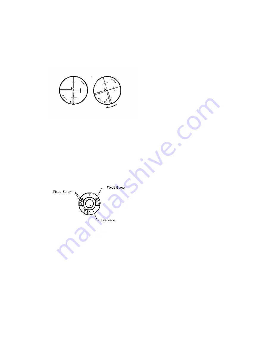
2. Move object A to the edge of e field of vi
l tangent screw (point A
′
)
3
t A mo
line of the reticle and point A
′
s
A
d
,A
′
offsets from the center to t
the reticle.
th
ew with the vertica
. Adjustment is not necessary if objec
till in the vertical line.
s illustrate
ves along the vertical
he cross hair tilts, then need to adjust
Adjustment
1. If the object A does not m
g with t
yepiece cover to
expose the four reticle adjusti
s.
2. Loosen the four reticle ad
g screws
in. Rotate the reticle
around the sight line and alig
al line of the reticle with point
A
′
.
3.T
g rews uniform
ent to see if the
a
4
ove alon
ng screw
he vertical line, firstly remove the e
justin
uniformly with an adjusting p
n the vertic
ighten the reticle adjustin
djustment is correct.
. Replace the eyepiece cover
sc
ly
,
Repeat the inspection and adjustm
.
10.4
Insp
. Set object A at a far distance at the same height as the instrument, then level and center the
0
″
).
L
ject A in right
posit
ent
PERPENDICULARITY OF LINE OF SIGHT TO HORIZONTAL AXIS (2c)
ection
1
instrument and turn on the power (horizontal angle L=10°13
′
1
2.
Sight object A in left position and read the horizontal angle value (horizontal angle R=
190°13
′
40
″
).
3.
oosen the vertical and horizontal clamp screws and rotate the telescope. Sight ob
ion and read the horizontal angle value.
4.
2C
=L-R±180°=-30
″≥
±
20
″
, adjustment is necessary.
Adjustm
A. Electronic Operation Procedures
:
184
Содержание STS-750
Страница 6: ...6...


