


3-46
Programming and Parameters
PowerFlex 700S Phase II AC Drive User Manual -
Publication 20D-UM006G-EN-P – July 2008
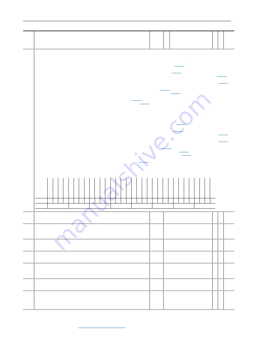
304 Limit
Status
Displays the limit status of conditions that may be limiting the current reference or torque reference.
•
Bit 0 “+MCS Iq Lim” indicates that torque producing current is at its positive limit.
•
Bit 1 “+MCS Ws Lim” indicates that flux producing torque is at its positive limit.
•
Bit 2 “0 Ia from +” indicates that torque producing current is limited to zero from the positive direction - refer to
[Iq Actual Lim].
•
Bit 3 “+Iq Calc” indicates the calculation for torque producing current has reached its positive limit.
•
Bit 4 “+Current Lim” indicates that the current reference has reached the positive Motor Current Limit set by
[Mtr Current Lim].
•
Bit 5 “+DriveProtOL” indicates that the current reference has reached the positive current limit set by the Open Loop Inverter Overload, shown in
OpnLp CurrLim].
•
Bit 6 “+DriveProtCL” indicates that the current reference has reached the positive current limit set by the Closed Loop Inverter Overload, shown in
[OL
ClsLp CurrLim].
•
Bit 8 “+Torq Limit” indicates that the torque reference has reached the Positive Torque Limit set by
[Torque Pos Limit].
•
Bit 9 “Mtrng PwrLim” indicates that the torque reference is being limited by the Motoring Power Limit set by
[Mtring Power Lim].
•
Bit 10 “+Torq CurLim” indicates that current reference has reached the Actual Torque Producing Current Limit set by Par 353 [Iq Actual Lim].
•
Bit 11 “Atune Tq Lim” indicates that the torque reference is being limited by
[Atune Trq Ref].
•
Bit 12 “+0 Torq Ena” indicates that the torque reference is limited to zero because
[Logic Ctrl State] bit 9 “Torq Ref En” is off.
•
Bit 13 “+0 Curr Ena” indicates that the current reference is limited to zero because Par 157 [Logic Ctrl State] bit 11 “CurrRef En” is off.
•
Bit 14 “Speed Limit” indicates the collective status of all speed limitations.
•
Bit 15 “Current Lim” indicates the collective status of all current limitations
•
Bit 16 “-MCS Iq Lim” indicates that torque producing current is at its negative limit.
•
Bit 17 “-MCS Ws Lim” indicates that flux producing torque is at its negative limit.
•
Bit 18 “0 Ia from -” indicates that torque producing current is limited to zero from the negative direction - refer to
[Iq Actual Lim].
•
Bit 19 “-Iq Calc’ indicates the calculation for torque producing current has reached its negative limit.
•
Bit 20 “-Current Lim” indicates that the current reference has reached the negative Motor Current Limit set by
[Mtr Current Lim].
•
Bit 21 “-DriveProtOL” indicates that the current reference has reached the negative current limit set by the Open Loop Inverter Overload, shown in
[OL
OpnLp CurrLim].
•
Bit 22 “-DriveProtCL” indicates that the current reference has reached the negative current limit set by the Closed Loop Inverter Overload, shown in
ClsLp CurrLim].
•
Bit 24 “-Torq Limit” indicates that the torque reference has reached the Negative Torque Limit set by
[Torque Neg Limit].
•
Bit 25 “Regen PwrLim” indicates that the torque reference is being limited by the Regenerative Power Limit set by
[Regen Power Lim].
•
Bit 26 “-Torq CurLim” indicates that current reference has reached the Actual Torque Producing Current Limit set by
[Iq Actual Lim].
•
Bit 27 “Bus Reg Tq Lim” indicates the bus voltage regulator is active and limiting the regenerative torque.
•
Bit 28 “-0 Torq Ena” indicates that the torque reference is limited to zero because
[Logic Ctrl State] bit 9 “Torq Ref En” is off.
•
Bit 29 “-0 Curr Ena” indicates that the current reference is limited to zero because Par 157 [Logic Ctrl State] bit 11 “CurrRef En” is off.
•
Bit 30 “Torque Limit” indicates the collective status of all torque limitations.
•
Bit 31 “Power Limit” indicates the collective status of all power limitations.
305
Mtr Trq Curr Ref
Displays the torque current reference present at the output of the current rate limiter. 100% is
equal to 1 per unit (pu) rated motor torque.
Units:
Default:
Min/Max:
P.U.
0.0000
-/+8.0000 pu
RO Real
306
DC Bus Voltage
Displays measured bus voltage.
Note: The maximum value was increased from 1000.0000 to 1170.0000 for firmware version
3.01.
Units:
Default:
Min/Max:
Volt
0.0000
0.0000/1170.0000
RO Real
307 Output
Voltage
Displays RMS line-to-line fundamental motor voltage. This data is averaged and updated
every 50 milliseconds.
Units:
Default:
Min/Max:
Volt
0.00
0.00/3000.00
RO Real
308 Output
Current
Displays measured RMS motor current.
Units:
Default:
Min/Max:
Amps
0.00
0.00/10000.00
RO Real
309
% Motor Flux
Displays the motor flux in % of nominal.
Units:
Default:
Min/Max:
Scale:
%
0.0
0.0/100.0
100 = 4096
RO 16-bit
Integer
310 Output
Freq
Displays the motor stator frequency.
Units:
Default:
Min/Max:
Hz
0.00
-/+250.00
RO Real
311 Output
Power
Motor Power is the calculated product of the torque reference and motor speed feedback. A
125mS filter is applied to this result. Positive values indicate motoring power; negative values
indicate regenerative power.
Note: The units were changed from kW to Hp for firmware version 2.03.
Units:
Default:
Min/Max:
Hp
0.00
-/+9999.00
RO Real
No.
Name
Description
Values
Linkab
le
R
ead-Wr
ite
Da
ta
T
ype
Options
Po
w
er
L
im
it
To
rq
ue
L
im
it
-0
Cu
rr
En
bl
-0
T
rq
Enb
l
Bu
s Reg Lim
-T
rq
Cu
rL
im
Re
gen Pwr
Lim
-T
rq
Li
mit
Sp
dReg Open
-Dr
iv
eProtCL
-Dr
iv
ePro
tOL
-C
ur
re
nt
Lim
-I
q Cal
c
0 I
q fr
om -
-MCS Ws
Li
m
-MCS Iq
Lim
Cu
rr
ent
Lim
Sp
eed Limit
+0
Cu
rr
E
nb
l
+0
T
rq
Enb
l
At
un T
rq Lim
+T
rq
Cu
rL
im
Mt
rng Pwr
Lim
+T
rq Limit
+S
pdReg
Ope
n
+D
ri
ve
ProtCL
+D
ri
ve
ProtOL
+C
urr
ent
Lim
+Iq Calc
0 I
q fr
om +
+MCS
Ws
Lim
+MCS Iq
L
im
Default
0
0
0
0
0
0
0
0
0
0
0
0
0
0
0
0
0
0
0
0
0
0
0
0
0
0
0
0
0
0
0
0
Bit
31 30 29 28 27 26 25 24 23 22 21 20 19 18 17 16 15 14 13 12 11 10 9
8
7
6
5
4
3
2
1
0
0 = False
1 = True
Содержание PowerFlex 700S
Страница 1: ...USER MANUAL Firmware Versions 1 xxx 4 002 PowerFlex 700S High Performance AC Drive Phase II Control ...
Страница 58: ...2 8 Start Up PowerFlex 700S Phase II AC Drive User Manual Publication 20D UM006G EN P July 2008 Notes ...
Страница 147: ...Programming and Parameters 3 89 PowerFlex 700S Phase II AC Drive User Manual Publication 20D UM006G EN P July 2008 ...
Страница 278: ...D 8 HIM Overview PowerFlex 700S Phase II AC Drive User Manual Publication 20D UM006G EN P July 2008 Notes ...
Страница 316: ...Index 6 PowerFlex 700S Phase II AC Drive User Manual Publication 20D UM006G EN P July 2008 ...
Страница 317: ......