


Parker Hannifin Corporation
Parflex Division
Ravenna, Ohio
Bulletin No. 4660-PGP2T
1
Parflex
®
Flexible Gas Piping System
Design and Installation Guide
Section 6.0 Pressure & Leakage Testing
6.1 Testing Requirements
6.1.1
Low-Pressure Systems —
Inspection and testing of the final piping system must be performed in accor-
dance with the code in effect. In the absence of the local code, the installation and testing of the final piping
system must be in accordance with the latest edition of the National Fuel Gas Code, ANSI Z223.1/NFPA 54
(in Canada CSA-B149.1). (Pressurize system to 1-1/2 times the working pressure but not less than 3 psi.)
Pressure testing must be performed during rough-in stage of construction (prior to finishing of interior
walls). All appliance terminations must be capped for initial pressure testing.
Parker advises, and many local codes require, an additional pressure or leakage test must be performed
after construction is completed and interior walls are finished. This additional test assures that no damage
was done to the tubing during the final close-in construction process and is required before gas service is
turned on. This leakage test is usually performed by the gas utility when the meter is initially set.
6.1.2
Elevated Pressure Systems
One-Part Test —
An elevated pressure system (2 psi) usually requires a 10 psi or greater air pressure test
to comply with local codes. A one-part test may be performed (depending on local codes) by replacing the
regulator with a suitable “jumper” pipe to allow elevated pressure testing of the entire system.
Caution: If
a one-part, high-pressure test is performed, the regulator must be removed to avoid regulator damage
caused by over pressurization.
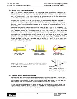
Two-Part Test —
A two-part air pressure test may need to be performed as shown in Figure 6.1 with the
regulator installed. The first test is performed on the elevated pressure section between the meter and the
pounds-to-inches line regulator. A 5 psi test pressure is applied. The second test is performed on the low-
pressure section between the outlet of the low-pressure regulator and the individual gas appliance outlets.
6.1.3
Appliance Connection and Leakage Check Procedure —
After final construction is completed and the
piping system has passed both the pressure test and inspection, connect the appliances to the PARFLEX
system using code approved flexible appliance connectors. Turn on the gas at the meter and inspect for
leakage at each appliance connection before operating the appliances. Appliance connections should be
leak checked using only a soapy water bubble solution.
Caution:
Leak test solutions may be corrosive to some materials used in gas tubing systems. Be sure to
rinse off leak test solutions with water and thoroughly dry all connections.
Do not leak test the regulator
vent limiter with a liquid test solution.
This will contaminate the ball check mechanism or plug the breath-
ing hole causing erratic regulator operation.
Before operating appliances, the tubing should be purged to remove air trapped in the tubing system. Al-
ways purge lines into a well ventilated area.
Regulator Performance Testing —
A pressure measurement should be made at each appliance connection while op-
erating all appliances at full load. This test assures that adequate pressure reaches each appliance under full-load
conditions. The inlet pressure for typical natural gas appliances should measure a minimum of 4 1/2 inches of water
column (10 inches WC for propane) under full-load conditions. If this pressure cannot be obtained, a slight adjust-
ment to the low-pressure regulator is necessary to increase line pressure.