


Parker Hannifin Corporation
Parflex Division
Ravenna, Ohio
Bulletin No. 4660-PGP2T
Parflex
®
Flexible Gas Piping System
Design and Installation Guide
4.1 General Practices
1. Use only components certified specified and supplied by Parker in the Parflex system. Care must be taken to
follow the installation and assembly procedures exactly as outlined in this guide.
2. Care must be taken to ensure that all exposed Parflex Tubing and components are not damaged during build-
ing construction. All tubing, fittings, accessories and system hardware should be stored in a clean, dry location
prior to installation.
3. Avoid stressing the tubing or fittings with tight bends, kinks, twists or excessive stretch.
4. Never use the Parflex Tubing and system components as a grounding electrode or as the grounding path for ap-
pliances or electrical systems.
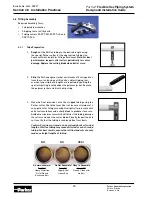
5. Protect the Parflex tubing (CSST) from impact or contact with heavy or sharp objects which can crush or punc-
ture the tubing. Avoid contact with corrosive chemicals, solder and fluxes containing acids and chloride com-
pounds. Keep the jacketing in place as much as possible to reduce the chance of exposing the tubing to corro-
sion.
6. All unterminated ends of tubing must be plugged, capped or taped closed to prevent contamination with dirt,
dust or other debris.
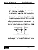
7. Avoid exceeding the minimum bend radius when installing Parflex Tubing.
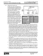
8. The Parker Parflex system is designed for use with fuel gas at operating pressures up to 5 psi. Avoid exposing
the tubing to pressure tests above 100 psig. Do not expose regulators above 10 psi. Caution: If a one-part,
high-pressure test is performed, the regulator must be removed to avoid regulator damage caused by over
pressurization. What does one-part mean? Testing the entire system from meter or second stage regulator
through to appliances.
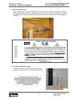
9. Parflex (CSST) tubing must be supported with metal pipe straps, brackets, bands and pipe hangers suitable for
the tubing size and weight. The use of metal pipe straps is preferred over plastic for best support and to comply
with most codes in the USA and Canada. All tubing runs must be supported at the spacing intervals noted.
Section 4.0 Installation Practices
PGP
Tube
Size
Recommended
Min. Bend Radius
(inches)
PGP-6 (3/8”)
3
PGP-8 (1/2”)
3
PGP-12 (3/4")
3
PGP-16 (1")
5
PGP-20 (1-1/4")
5
PGP-32 (2")
6
Tube Size
Horizontal and Inclined Runs
Vertical Runs
3/8” PGP-6
4 ft. Max.
Support at each floor
with 10 ft. maximum
spacing between
supports
1/2” PGP-8
6 ft. Max.
3/4" [PGP-12]
8 ft. Max. (USA) 6 ft. Max. (Canada)
1" [PGP-16]
8 ft. Max. (USA) 6 ft. Max. (Canada)
1-1/4" [PGP-20]
8 ft. Max. (USA) 6 ft. Max. (Canada)
2" [PGP-32]
8 ft. Max. (USA) 6 ft. Max. (Canada)
RADIUS