


Parker Hannifin Corporation
Parflex Division
Ravenna, Ohio
Bulletin No. 4660-PGP2T
1
Parflex
®
Flexible Gas Piping System
Design and Installation Guide
3.1.2
Pressure System
Low Pressure System
— Low pressure sys-
tems have gas service pressure down-
stream of the meter at less than 1/2 psi
(14 inches WC). These systems typically
have 7 inches WC (1/4 psi) system pres-
sure for natural gas and 11 inches WC
for propane. The allowable pressure drop
along any piping run may be specified by
local codes. The minimum pressure sup-
plied to each appliance should be con-
sidered. Typically, natural gas appliances
require 4 inches WC, and propane (LPG)
appliances require 10" WC minimum sup-
ply pressure measured at the appliance.
The second stage regulator for propane
systems is often set at 11 inches WC and
a 1/2 inch WC maximum pressure drop is
allowed through each line. A low-pressure
series arrangement typically requires
larger diameter tubing to meet appliance
demands.
S
ection 3.0 System Configuration & Sizing
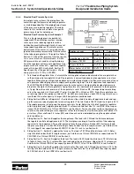
Parallel System
— Parallel system layouts
utilize a central distribution manifold
from which appliances are supplied
by branch runs. The manifold is often
located closest to the appliance with
the highest load; typically, the furnace
or boiler. A parallel layout is commonly
used in elevated supply pressure
systems (above 7 inches WC, 1/4 psi).
Generally, a parallel layout requires a
higher total footage of smaller diame-
ter tubing and fewer fittings compared
with a series layout.
Parallel System Layout
Low Pressure Natural Gas or Propane System (Series)