


Parker Hannifin Corporation
Parflex Division
Ravenna, Ohio
Bulletin No. 4660-PGP2T
Parflex
®
Flexible Gas Piping System
Design and Installation Guide
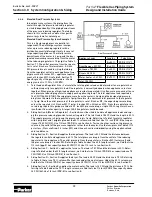
3.2.6
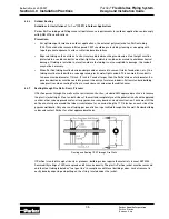
Parflex System / Steel Pipe Hybrid System Example
Hybrid System
— Hybrid system layouts use
a combination of CSST and rigid pipe on low
or medium pressure systems. These systems
typically have long runs and high loads. The
rigid pipe is used on long straight runs and
the CSST is used to connect to the units.
In this example, we are supplied with 7 inches
WC and the gas company has stated the spe-
cific gravity of the natural gas is 0.60. Local
codes require a pressure drop of 0.5 in. WC.
Hybrid System Example 1
This is a low-pressure series system with four
natural gas appliances. The main trunk line in
this system is specified as black iron and the
branches are determined to be Parflex tubing.
The utility company supply pressure exit-
ing the meter is 7 inches water column. The
maximum allowable pressure drop across the
longest length from the meter to the farthest
appliance is 1/2 inch water column. Because
we are using both black iron pipe and the
Parflex tubing, we need to two types of pres-
sure tables. We will use Steel Tables (Table
17, Section 7.1) and Parflex Table of 0.5 psig or
less with a pressure drop of 0.5 in. WC (Table
1, Section 7.1).
1. Determine the total gas load for each
appliance in cubic feet per hour:
Furnace ............................. 75 CFH (75,000 BTUH/1000 BTUH per CFH)
Oven/range ....................... 50 CFH (50,000 BTUH/1000 BTUH per CFH)
Dryer ................................. 25 CFH (25,000 BTUH/1000 BTUH per CFH)
Water heater ..................... 34 CFH (34,000 BTUH/1000 BTUH per CFH)
Total .................................. 184 CFH
2. Measure the length of each run and determine the maximum length from the meter to the farthest
appliance.
A = 20 ft., B = 30 ft., C = 10 ft., D = 18 ft., E = 10 ft., F = 15 ft. G = 12 ft.
Furnace = A + E = 20 ft. + 10 ft. = 30 ft
Oven/range = A + B + F = 20 ft. + 30 ft. + 15 ft. = 65 ft.
Dryer = A + B + C + G = 20 ft. + 30 ft. + 10 ft. + 12 ft. = 72 ft.
Water heater = A + B + C + D = 20 ft. + 30 ft. + 10 ft. + 18 ft. = 78 ft.
The longest run is from the meter to the water heater over 78 ft.
3) Sizing Section A – Length A must be sized to handle the total load of all appliances and the total
pressure drop from the meter to the farthest appliance. The total appliance load is 184 CFH. Using the
longest length sizing method, the length is 78 ft. to the water heater. Referring to Table 17 (7 inches
WC inlet pressure and 1/2 inch WC pressure drop) under the 80 ft. length column (next longest length
column), we find that 1 inch size black iron pipe has a flow capacity exceeding 184 CFH (220 CFH). Use
1 inch black iron pipe to run Section A.
4. Sizing Section B – Section B must supply the water heater, dryer, and range. The total pressure drop
for the system is considered to be from the meter to the water heater (farthest appliance). The total
appliance load is 34 + 25 + 50 = 109 CFH. Using the longest length sizing method, the length is 78 ft.
(distance from meter to water heater). Referring to Table 17 under the 80 ft. length column, we find
that size 3/4 inch black iron pipe has flow capacity over 109 CFH (118). Use 3/4 inch black iron pipe to
run Section B.
Section 3.0 System Configuration & Sizing
Hybrid System
Appliance Loads
Lengths
Tube Size
-
A = 20 ft.
1" Black Iron
-
B = 30 ft.
3/4" Black Iron
-
C = 10 ft.
3/4" Black Iron
Oven/Range = 50 CFH
D = 18 ft.
PGP-8 (1/2")
Furnace = 75 CFH
E = 10 ft.
PGP-12 (3/4")
Dryer = 25 CFH
F = 15 ft.
PGP-16 (1")
Water heater = 34 CFH
G = 12 ft.
PGP-8 (1/2")
Total 184 CFH