


Parker Hannifin Corporation
Parflex Division
Ravenna, Ohio
Bulletin No. 4660-PGP2T
Parflex
®
Flexible Gas Piping System
Design and Installation Guide
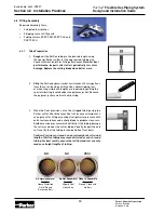
4.3 Routing
4.3.1
Vertical Runs
Routing for
vertical runs
is preferred in
hollow interior wall cavities
. A carefully developed routing plan
will eliminate the need for extra strike protection and comply with local building codes and to provide
optimum protection for the Parflex tubing. The tubing should be supported every 10 feet on vertical runs.
When routing the tubing inside insulated exterior walls ensure the tubing will be routed between the paper
facing of the insulation and the interior wall surface.
4.3.2
Horizontal Runs
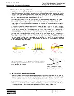
Horizontal and Inclined Runs
– Alongside of floor and ceiling joists, through floor and ceiling joists, and
beneath floor joists are the most common routes. Careful consideration in routing must be given to future
construction in unfinished basements, garages, and in areas where contact with exposed tubing could
occur.
Routing the Parflex tubing above or along ceiling joist is preferred in “slab-on-grade” construction
where the shortest path and optimum protection is achieved by running tubing in the attic space. Tubing
routed horizontally on structural members which meet the spacing requirement of 4 feet do not require
support or strapping.
4.3.3
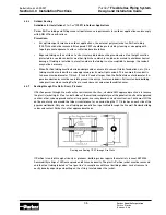
Clearance Holes
Clearance holes for routing the tubing are to be
1/2 inch greater than the O.D. of the tubing
. Follow all
building codes when drilling through structural members. Use caution not to exceed the minimum bend
radius when installing the tubing.
4.3.4
Concealed Fittings
Parker FastMate™ fittings have been tested and listed in accordance with ANSI LC1b for use in concealed
spaces. Tee fittings provide a reliable connection for branch runs while union couplings permit quick re-
pairs and length splices. Straight and elbow connectors can be used for concealed attachment to appliance
valves. Special care should be taken to ensure that all concealed connectors are properly protected, sized
and pressure tested following the procedures outlined in this guide. The use of concealed connections
must comply with local building codes. A review of applicable codes is recommended. All other connectors
such as shut-off valves, manifolds, regulators and quick disconnects must be installed in an accessible
space.
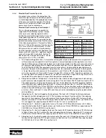
Section 4.0 Installation Practices
Parflex
Tube
Size
Installation
Drill Hole
Diameter
(Inch)
PGP-6 (3/8")
1-1/8"
PGP-8 (1/2")
1-3/8"
PGP-12 (3/4")
1-1/2"
PGP-16 (1")
1-3/4"
PGP-20 (1-1/4")
2-1/4"
PGP-32 (2")
3"