


Parker Hannifin Corporation
Parflex Division
Ravenna, Ohio
Bulletin No. 4660-PGP2T
1
Parflex
®
Flexible Gas Piping System
Design and Installation Guide
3.1 System Configuration
The final piping system design depends on local plumbing restrictions and codes, floor plan, appliance locations,
availability of elevated street pressure, total gas load, and system cost. This design manual does not dictate the type
of the gas distribution system configuration. The configuration is left up to the system designer. This manual will aid
in sizing tubing for the system once the configuration has been selected.
3.1.1
System Planning
Prior to the piping installation, carefully follow the steps provided below
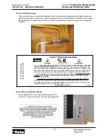
1. Confirm that the local building code authority has accepted the use of the Parflex System. Contact your
Parflex System distributor for this information.
2. Check with the local gas utility or supplier to determine the metered gas supply pressure.
Natural Gas —
Supply pressure in the USA and Canada is typically 6 to 7 inches water column (1/4 psi
or 4 ounces). Higher supply pressures 1/2 psi (14 inches WC), 1 psi (28 inches WC), and 2 psi (56 inches
WC) will allow reduced tubing size in the Parflex System design plan. The Parflex System can also be
used in 5 psi supply pressure systems which are normally restricted to commercial installations.
Propane
(LPG–Liquid Petroleum Gas) — Typical propane supply pressure for residential buildings is 11
inches water column set at the second stage regulator outside the building. Higher supply pressures
will allow reduced tubing size. Check with your propane supplier and local building code authority.
3. Prepare a dimensioned sketch of the installation showing the location of each appliance and possible
piping routes.
4. Determine the load (BTU/hr or CFH) demand and the minimum required inlet pressure for each ap-
pliance. This data is commonly found on the manufacturer’s nameplate on each gas appliance or is
provided by the builder/contractor.
5. Determine the total capacity for all appliances planned in the installation. The BTU equivalents for
natural gas or propane flow (CFH) can be obtained from the local gas utility or propane supplier. For
natural gas, one cubic foot per hour (1 CFH) is approximately 1,000 BTUH. For propane, one cubic foot
per hour (1 CFH) is approximately 2,500 BTUH. The capacity tables in this guide can be used for sizing
to meet appliance BTU input loads.
6. Determine the type of piping layout which best fits the installation.
Section 3.0 System Configuration & Sizing
Sizing and Pressure Loss
—
The design of a gas system under maximum probable flow conditions must
provide gas volume and pressure from the meter to the appliance must be delivered greater than the
minimum volume and pressure required for proper equipment operation.
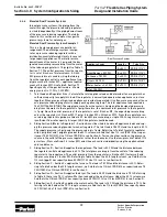
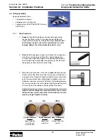
Series System
— Series system layouts are
common in low-pressure, rigid steel
piping systems. Numerous elbow and
tee fittings are used to branch off of
a main run. Generally, a series layout
requires larger tubing sizes and more
fittings compared with a parallel lay-
out.
Series System Layout