


Parker Hannifin Corporation
Parflex Division
Ravenna, Ohio
Bulletin No. 4660-PGP2T
1
Parflex
®
Flexible Gas Piping System
Design and Installation Guide
3.2.3
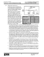
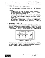
Longest Length Parallel System Example (Medium Pressure)
This is a medium pressure parallel system which
includes a distribution manifold. The specific
gravity of the gas is 0.60. The allowable pressure
drop across the system has been determined to
be 7 inches WC (supply pressure 12 inches WC
– appliance requirement 5 inches WC). Because
there is no 7 inches WC pressure drop chart
available we must use the next lowest chart: in
this case the 6 inches WC pressure drop chart
(Table 8, Section 7.1)
1. Sizing Section A – Determine distance from
meter to the farthest appliance (water
heater 130 ft.) Determine the total appli-
ance load supplied by Section A (184 CFH).
Since 130 ft. does not appear in the length
column, use the next longest length column
of 150 ft. Refer to Table 8 under the 150 ft.
length column. We find that 1 inch (PGP-16)
has flow capacity above 184 CFH (378). Use
1 inch (PGP-16) to run Section A.
2. Sizing Section B – Section B supplies the
range/oven. The total pressure drop is con-
sidered from the meter to the oven/range.
The total load is 50 CFH and the length is
80 ft. + 20 ft. = 100 ft. Referring to Table 8
under the 100 ft. length column, we find that 1/2 inch (PGP-8) has capacity above 50 CFH (98). Use 1/2
inch (PGP-16) to run Section B.
3. Sizing Section C – Section C supplies the furnace. The total load is 75 CFH and the total length is 80
ft. + 5 ft. = 85 ft. Refer to Table 8 under the 85 ft. column. Since 85 ft. does not appear in the length
column, use the next longest length column of 90 ft. We find that 1/2 inch (PGP-8) has capacity above
75 CFH (103). Use 1/2 inch (PGP-8) to run Section C.
4. Sizing Section D – Section D supplies the dryer. The total load is 25 CFH and the total length is 80 ft. +
35 ft. = 115 ft. Refer to Table 8 under the 115 ft. column. Since 115 ft. does not appear in the table, use
the next longest length column of 125 ft. We find that 3/8 inch (PGP-6) has capacity above 25 CFH (33).
Use 3/8 inch (PGP-6) to run Section D.
5. Sizing Section E – Section E supplies the dryer. The total load is 34 CFH and the total length is 80 ft. +
50 ft. = 130 ft. Referring to Table 8 under the 150 ft. column, we find that 1/2 inch (PGP-8) has capacity
above 34 CFH (80). Use 1/2 inch (PGP-8) to run Section E.
Section 3.0 System Configuration & Sizing
Appliance Loads
Lengths
Tube Size
-
A = 80 ft.
PGP-16 (1")
Oven/Range = 50 CFH
B = 20 ft.
PGP-8 (1/2")
Furnace = 75 CFH
C = 5 ft.
PGP-8 (1/2")
Dryer = 25 CFH
D = 35 ft.
PGP-6 (3/8")
Water heater = 34 CFH
E = 50 ft.
PGP-8 (1/2")
Total 184 CFH
Parallel Syste
m