


Parker Hannifin Corporation
Parflex Division
Ravenna, Ohio
Bulletin No. 4660-PGP2T
1
Parflex
®
Flexible Gas Piping System
Design and Installation Guide
Section 3.0 System Configuration & Sizing
3.2 System Sizing Methods and Examples
3.2.1
Sizing Methods
Longest Length Method
– The method to size gas piping that take into count the pressure at the down
stream end of the meter and the furthest appliance. The piping in the system should be sized large
enough to accommodate the entire system load.
Dual Pressure Method
– The pressure down stream of the primary regulator is elevated most commonly to
2 psig or 5 psig. A secondary regulator is located before the manifold.
Elevated Pressure Method
– Higher pressure is run through a system to each appliance. In this method, a
regulator will be placed in front of each appliance.
Summation Method –
The summation method is used for gas pipe sizing, the pressure losses through the
pipe should be considered as to allow minimum pressure and volume of gas to the appliance. Sizing
can be accomplished by calculations based on summation of line pressure drops and exact appliance
loads. The pressure drop summation method is more precise than the longest length method and may
permit the use of smaller diameter tubing in some installations. Pressures should be sufficient to
manufacturer’s input rating and the local authority.
3.2.2
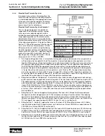
Longest Length Series System Example (Low Pressure)
This is a low pressure series system with four natural
gas appliances. The utility company supply pressure
exiting the meter is 6 inches water column, and the
minimum continuous inlet pressure required by the
appliances is 5 1/2 inches water column. The maxi-
mum allowable pressure drop across the longest
length from the meter to the farthest appliance is 1/2
inch water column. The gas supplied has a specific
gravity of .60 and an energy content of 1 cubic foot
per hour equals 1,000 BTU per hour. Reference Sizing
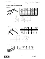
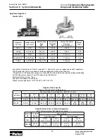
Table 1, Section 7.1, for sizing charts.
1. Determine the total gas load for each appliance
in cubic feet per hour:
Furnace ...................... 75 CFH (75,000 BTUH/1000 BTUH per CFH)
Oven/range ................ 50 CFH (50,000 BTUH/1000 BTUH per CFH)
Dryer .......................... 25 CFH (25,000 BTUH/1000 BTUH per CFH)
Water heater .............. 34 CFH (34,000 BTUH/1000 BTUH per CFH)
Total ........................... 184 CFH
2. Measure the length of each run and determine the maximum length from the meter to the farthest ap-
pliance.
A = 8 ft., B = 10 ft., C = 12 ft., D = 20 ft., E = 2 ft., F = 6 ft. G = 8 ft.
Furnace = A + F = 8 ft. + 6 ft. = 14 ft.
Oven/range = A + B + E = 8 ft. + 10 ft. + 2 ft. = 20 ft.
Dryer = A + B + C + G = 8 ft. + 10 ft. + 12 ft. + 8 ft. = 38 ft.
Water heater = A + B + C + D = 8 ft. + 10 ft. + 12 ft. + 20 ft. = 50 ft.
The longest run is from the meter to the water heater is 50 ft.
3. Sizing Section A—Length A must be sized to handle the total load of all appliances and the total pres-
sure drop from the meter to the farthest appliance. The total appliance load is 184 CFH. Using the
longest length sizing method, the length is 50 ft. to the water heater. Referring to Table 1 (0.5 psig or
less; pressure drop 0.5 in. WC) under the 50 ft. length column, we find that 1 inch size (PGP-16) has a
flow capacity exceeding 184 CFH (186 CFH). Use 1 inch tubing (PGP-16) to run Section A.
4. Sizing Section B—Section B must supply the water heater, dryer, and range. The total pressure drop
for the system is considered to be from the meter to the water heater (farthest appliance). The total
appliance load is 34 + 25 + 50 = 109 CFH. Using the longest length sizing method, the length is 50 ft.
(distance from meter to water heater). Referring to Table 1 under the 50 ft. length column, we find that
size 1 inch (PGP-16) has flow capacity over 109 CFH (186). Use 1 inch (PGP-16) to run Section B.
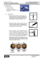
Low Pressure Natural Gas System (Series)