


Parker Hannifin Corporation
Parflex Division
Ravenna, Ohio
Bulletin No. 4660-PGP2T
Parflex
®
Flexible Gas Piping System
Design and Installation Guide
Section 3.0 System Configuration & Sizing
3.2.4
Elevated Dual Pressure Systems
In dual pressure systems, the piping from the
meter through the pressure reducing regulator
is sized independently of the piping downstream
of the pressure reducing regulator. The tables
shown in this section are used to size specific
pressure systems for natural gas.
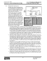
Elevated Dual Pressure Systems Example 1
This is a 2 psig supply pressure parallel ar-
rangement. The natural gas system incorpo-
rates a pressure reducing regulator with a
distribution manifold located closely to several
large capacity appliances. The inlet pressure
downstream of the meter is 2 psig, and the des-
ignated maximum pressure drop from the meter
to the reducing regulator is 1.0 psig. Use Table 9,
Section 7.1. The outlet pressure from the regula-
tor is set at 8 inches of water column. A 3 inch
WC pressure drop is used in sizing the tubing
from the regulator outlet to each appliance (sup-
ply pressure of 8 inches WC – appliance require-
ment of 5 inches WC). Use Table 5, Section 7.1.
Specific gravity of the gas delivered is .60 and
energy content is 1 CFH = 1,000 BTU.
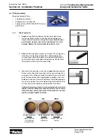
1. Total Load and Regulator Size – Calculate the total appliance load and determine if one regulator has
sufficient capacity to supply this load. One regulator is normally adequate when appliances are close
together. When groups of high-load appliances are widely separated, it is often more economical to use
one pressure reducing regulator to supply each appliance group. The total appliance load required is
184 CFH (184,000 BTUH). The supply pressure from the meter is 2 psig and the designated pressure
drop from the meter to the regulator is 1psig; therefore, the minimum inlet pressure to the regulator
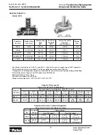
is 1 psig. Since the outlet pressure of the regulator is set at 8 inches WC, the expected pressure drop
across the regulator is 20 inches WC (1 psig – 8 inches WC = 20 inches WC). From the regulator pres-
sure drop graph in this guide, we find at a 20 inch WC pressure drop, a single 325-3L regulator has an
insufficient flow rate capacity. A larger 325-5A regulator should be used.
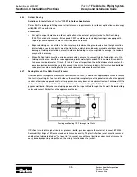
2. Sizing Section A (Meter to Regulator) – Section A must be sized to handle all appliance loads and sup-
ply the pressure reducing (pounds to inches) regulator. The total load is 184 CFH and the length is 80 ft.
The supply pressure is 2 psig and the pressure drop is 1 psig. Referring to Table 9 (meter to regulator
with 2 psig inlet and 1 psig drop) under the 80 ft. column, we find that size 1/2 inch (PGP-8) has capac-
ity over 184 CFH (210). Use 1/2 inch (PGP-8) to run Section A. To size the other sections, the pressure
source is the outlet of the pressure regulator rather than the meter. Use the low-pressure Table 5 (1/2
psi or less; Pressure Drop: 3.0 inches WC) and size each section individually using the appliance load
and run distance.
3. Sizing Section B – Section B supplies the range/oven. The load is 50 CFH and the distance between
the regulator outlet and appliance is 40 ft. The total pressure drop is from the outlet of the reducing
regulator to the range/oven. The outlet pressure from the regulator is 8 inches WC (factory set) and
the pressure drop is 3 inches WC. Referring to Table 5 under the 40 ft. length column, we find that size
1/2 inch (pgp-8) has capacity above 50 CFH (110). Use 1/2 inch to run Section B.
4. Sizing Section C – Section C supplies the furnace. The load is 75 CFH and the distance is 20 ft. Refer-
ring to Table 5 under the 20ft. length column, we find that size 1/2 inch (PGP-8) has capacity above 75
CFH (155). Use 1/2 Inch (PGP-8) to run Section C.
5. Sizing Section D – Section D supplies the dryer. The load is 25 CFH and the distance is 75 ft. Referring
to Table 5, there is no 75 ft. column. We then look under the next column. Under the 80 ft. column, we
find that size 3/8 inch (PGP-6) has capacity above 25 CFH (31). Use 3/8 Inch (PGP-6) to run Section D.
6. Sizing Section E – Section E supplies the water heater. The load is 34 CFH and the distance is 70 ft. Re-
ferring to Table 5 under the 70 ft. length column, we find that size 1/2 inch (PGP-8) has capacity above
34 CFH (84). Use 1/2 Inch (PGP-8) to run Section E.
Dual Pressure System
Appliance Loads
Lengths
Tube Size
-
A = 80 ft.
PGP-8 (1/2")
Oven/Range = 50 CFH
B = 40 ft.
PGP-8 (1/2")
Furnace = 75 CFH
C = 20 ft.
PGP-8 (1/2")
Dryer = 25 CFH
D = 75 ft.
PGP-6 (3/8")
Water heater = 34 CFH
E = 70 ft.
PGP-8 (1/2")
Total 184 CFH