


Parker Hannifin Corporation
Parflex Division
Ravenna, Ohio
Bulletin No. 4660-PGP2T
Parflex
®
Flexible Gas Piping System
Design and Installation Guide
•
The average natural gas appliance is designed to operate at 3 to 4 inches water column pressure with
a pressure drop of 1 to 2 inches of water column across the appliance regulator which prevents slow
regulator response. Thus, the appliance will operate best at 5 to 6 inches water column inlet pressure.
In this case, the 2 psi system regulator should be reset to deliver approximately 8 to 10 inches of water
column outlet pressure under full load to allow for 3 inches of water column pressure drop in the
Parflex tubing.
•
Regulators supplied by Parker are factory set at 8 inches of water column output for natural gas
and 11 inches of water column for propane. Some appliances may have different inlet pressure
requirements.
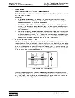
4.8 Line Pressure Regulators
4.8.1
Installation Requirements
On Parflex (CSST) systems having supply pressure exceeding 1/2 psi (14" WC), a regulator must be in-
stalled downstream to limit appliance supply pressure to a maximum of 1/2 psi (14" WC). The regulators
currently certified for uses with Parflex are Maxitrol type 325-3L and 325-5A.L. At supply pressures in
excess of 2-psi, ANSI Z21.80 line regulator standard requires an approved and tested OPD (over-pressure
protection device) as a means to limit the downstream pressure to 2-psi maximum, in the event of regula-
tor failure.
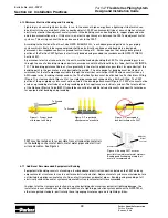
a. All regulators must be installed following the manufacturer’s instructions and placed in a fully acces-
sible area. It is recommended that the regulator be installed in a horizontal (stem up) position when a
vent limiter device is used. A shut-off valve should be installed ahead of the regulator, and union con-
nectors should be used in the piping system to allow for removal of the regulator.
b. The capacity of the regulator selected should exceed the total appliance load requirements. Refer to
regulator data in Section 2.0, “System Components,” of this guide.
4.8.2
Venting
Vent Limiting Device
•
All Maxitrol 325-3L and 325-5AL regulators must be vented to the outdoors or equipped with vent lim-
iters.
•
The vent limiting device can only be used when vented gas is discharged to an open, well-ventilated
area. Local codes shall take precedence in determining how regulators must be vented.
•
Do not check the vent limiter with liquid test solutions as this will contaminate the device and cause
erratic operation.
•
If the regulator is used in an outdoor installation, the preferred practice is to remove the limiter and
install the regulator upside down (stem down) to allow drainage and to prevent water from getting into
the regulator.
Vent Line Sizing
•
When a vent line is used, the line must be less than 30 feet long and sized to meet or exceed the regu-
lator vent port size. The vent line should be designed and routed to prevent the entry and accumulation
of water, insects and other foreign material which could block the line.
Never vent the regulator to an
appliance flue, drain or building exhaust system.
4.8.3
Adjustments
•
Regulators can be adjusted to deliver different outlet pressures within a limited range. To access the
adjustment screw, first remove the seal cap. Turning the screw clockwise increases outlet pressure
while turning counterclockwise will decrease outlet pressure.
•
Always replace the seal cap after making a regulator adjustment. If adjustments do not produce
the desired outlet pressure, check the inlet supply pressure, remove the regulator from service and
consult the factory. Do not continue to turn adjustment screw clockwise if outlet pressure does not
increase. This may cause a regulator malfunction due to a loss in pressure control.
•
The common 2 psi system line regulator can be adjusted with an outlet pressure ranging between
7 and 11 inches of water column. The regulator must be adjusted according to the manufacturer’s
recommended procedure. A pressure gauge mounted downstream of the regulator monitors the set
pressure under various loads.
Section 4.0 Installation Practices