PART 2: CX-Server PLC Tools
CHAPTER 3 – IO Table Component
OMRON
CX-Server PLC Tools_Page 24
1, 2, 3…
1. Right-click the slot where the Unit will be allocated and select
Add Unit
(or just
double-click the desired slot). The
Select Unit
Dialog Box will be displayed.
2. Select the desired Unit (Unit to be allocated) from the directory tree menu and click the OK
Button.
Setting Parameters for CS/CJ/CP-series CPU Bus Units and Special I/O Units
After the I/O table has been created, the I/O table and Special I/O Unit/CPU Bus Unit parameters can be
transferred from the PLC and edited in the computer, as shown in the following example.
1, 2, 3…
1. Connect the CX-Programmer online and open the I/O Table Window.
2. Select
Options – Transfer from the PLC
from the I/O Table Window’s menu. The Transfer
from the PLC Dialog Box will be displayed. At this point, the
I/O Table
and
SIO Unit
Parameters
Options can be selected.
3. Select the options (check the boxes) for the data that you want to transfer and click the
Transfer Button. In this case, both options have been selected.
The I/O table and Unit parameters data will be transferred from the PLC and the transfer
results will be displayed.
4. Check the transfer results and click the OK Button. The I/O table transferred from the PLC
will be displayed.
5. To edit the parameters of a Special I/O Unit or CPU Bus Unit, select the Unit and either
double-click the Unit or select
Edit – SIO Unit Parameters
from the menu. The selected
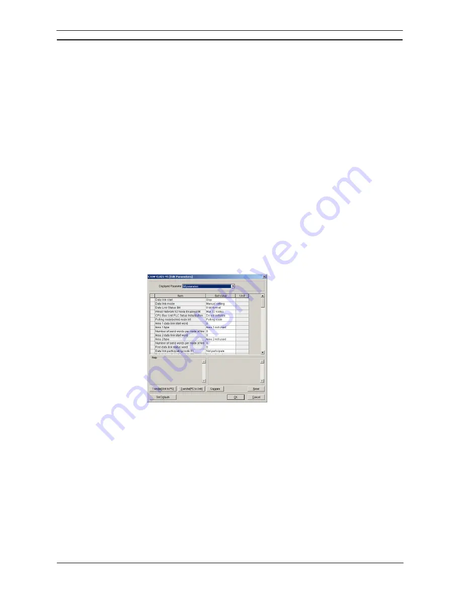
Unit’s Edit Parameters Dialog Box will be displayed.
In this case, a Controller Link Unit’s Edit Parameters Dialog Box has been displayed to edit
the Unit’s CPU Bus Unit Allocation DM Settings.
6. Edit the parameters and, if necessary, click the Compare Button. If the Compare Button is
clicked while the PLC is online, the software immediately checks whether the I/O table
settings match the Unit settings (such as the allocated DM area and CIO area) actually in
the PLC’s CPU Unit.
If the contents do not match, the settings read from the actual Unit will be displayed in
orange.
7. When you want to download the parameters set for each Unit to the PLC’s CPU Unit, click
the Download to Unit Button.
8. Click the Reset Button to enable the parameter settings that have been transferred.
Note 1:
When Special I/O Unit or CPU Bus Unit settings are edited in the I/O Table Window,
the parameters allocated in the DM Area or CPU Bus Unit Setup Area for the Unit are
only transferred to the actual PLC when the
Transfer PC to Unit
Button is clicked in
the Edit Parameters Dialog Box. They are not automatically enabled, i.e., the new
parameter settings will not be used. Click the Reset Button to enable the parameter
settings that have been transferred. When the Reset Button is clicked, however,
Содержание CX-PROGRAMMER V9
Страница 1: ...Cat No W446 E1 12 CX Programmer Ver 9 CXONE AL_C V4 AL_D V4 SYSMAC OPERATION MANUAL...
Страница 2: ......
Страница 3: ...SYSMAC CX Programmer Ver 9 CXONE AL C V4 AL D V4 Operation Manual Revised July 2010...
Страница 4: ......
Страница 6: ......
Страница 32: ......
Страница 33: ...PART 1 CX Programmer...
Страница 34: ......
Страница 91: ......
Страница 111: ......
Страница 191: ...PART 1 CX Programmer CHAPTER 4 Reference OMRON CX Programmer _Page 108...
Страница 217: ......
Страница 233: ......
Страница 234: ...PART 2 CX Server PLC Tools...
Страница 235: ......
Страница 243: ......
Страница 249: ......
Страница 261: ...PART 2 CX Server PLC Tools CHAPTER 2 PLC Memory Component OMRON CX Server PLC Tools_Page 18...
Страница 280: ......
Страница 333: ......
Страница 377: ......
Страница 409: ......
Страница 430: ......
Страница 431: ...PART 3 CX Server Runtime...
Страница 432: ......
Страница 476: ......
Страница 482: ......
Страница 498: ......
Страница 524: ......
Страница 534: ......
Страница 535: ......
Страница 536: ......


