Nidek Medical AFC-330 Скачать руководство пользователя страница 72

56

OPERATING PROCEDURE

Image Capture Preparation

2

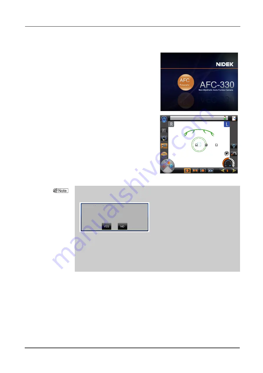
Turn on power to the device.

The initial screen appears on the LCD touch-
screen. Initialization of the device is started.

Wait (for about 45 seconds) until the initial
screen changes to the anterior eye observation
screen.

When power to the device is turned on, the main
unit makes slight movement in all directions to
determine the initial position for the auto track-
ing. It is not a failure of the device.

The anterior eye observation screen.

3

Remove the cap from the objective lens and check the lens for cleanliness.

Attach the removed objective lens cap to the cap holder.

If the objective lens is not clean, clean the lens. An unclean objective lens affects image cap-
ture considerably. 

After starting the device, observe the patient’s eye under visible light (halogen lamp) with the
infrared filter inside the device removed by pulling the infrared filter lever.

For details, see “4.3 Cleaning Objective Lens” (Page 155).

If the objective lens is even slightly soiled, image capture may be affected.

䎳䏕䏒

Anterior eye observation screen

• The message shown below may appear when the anterior eye observation screen is

activated. Select YES or NO as necessary to clear the message.

When “YES” is selected, the patient information register screen is displayed and deletion of data
from the list is started.

While data is being deleted, an indicator appears.

Depending on the number of patients whose data is to be deleted, the data deletion may
take long.

For details of setting of the retention period of patient data, see “


Software settings” (Page 108).

৻ቯᦼ㑆⚻ㆊ䬦䬮ᖚ⠪ᖱႎ䬛
䬑䭙䭍䬨䫻
ᖚ⠪䮱䮀䮏䬚䭘೥㒰䬦䭍䬨䬚䰋

䎷䏋䏈䎃䏕䏈䏗䏈䏑䏗䏌䏒䏑䎃䏓䏈䏕䏌䏒䏇䎃䏉䏒䏕䎃䏖䏒䏐䏈䎃䏇䏄䏗䏄䎃䏋䏄䏖

䏄䏏䏕䏈䏄䏇䏜䎃䏓䏄䏖䏖䏈䏇䎑

䎺䏒䏘䏏䏇䎃䏜䏒䏘䎃䏏䏌䏎䏈䎃䏗䏒䎃䏇䏈䏏䏈䏗䏈䎃䏗䏋䏈䏖䏈䎃䏇䏄䏗䏄䎢

Содержание AFC-330

Страница 1: ...NON MYDRIATIC AUTO FUNDUS CAMERA NON MYDRIATIC AUTO FUNDUS CAMERA AFC 330 AFC 330 OPERATOR S MANUAL OPERATOR S MANUAL...

Страница 2: ...pan Telephone 81 3 5844 2641 Facsimile 81 3 5844 2642 NIDEK INCORPORATED 47651 Westinghouse Drive Fremont California 94539 U S A United States Agent Telephone 1 510 226 5700 Facsimile 1 510 226 5750 N...

Страница 3: ...within the device that requires servicing by the user If you encounter any problems or have questions about the device please contact NIDEK or your authorized distributor In this manual a signal word...

Страница 4: ...the cautions for safety and operating procedures must be thoroughly understood Do not use accessories that are not specified by NIDEK for the device Use of the device outside the scope of the specifie...

Страница 5: ...than the one provided Do not use the provided power cord for any other instrument Malfunction or fire may result Before connecting any cables to the device be sure to turn off power to the device and...

Страница 6: ...it locking knob The main unit may move during the transport and the device may fail For details of the locking knob see 5 Locking knob Page 7 in 1 4 Device Configu ration Do not lock the main unit to...

Страница 7: ...imum level required Be sure to return the light amount to the minimum level after every patient Large amount of light not only may cause dizziness but also may cause thermal or optical damage to the p...

Страница 8: ...sher Immediately replace the power cord if the internal wires are exposed the power turns on or off when the power cord is moved or the cord or plug is too hot Immediately remove the plug from the pow...

Страница 9: ...ive appropriate national standards such as EN 60601 1 and IEC 60601 1 Further more all configurations shall comply with the system standard IEC 60601 1 Anyone who connects additional equipment to the...

Страница 10: ...nd any part of the device or between the patient and any other person s touching the device Use devices that comply with IEC60601 1 in the patient environment If any device that does not comply with I...

Страница 11: ...s the dust could collect moisture and short circuit or fire may occur If the device is used after a long period of disuse check for any abnormality before use Store and transport when the device is pa...

Страница 12: ...nce space Maintenance work in an insufficient space may result in injury When cleaning the device exterior or the LCD touch screen do not use organic abrasive cleaner such as thinner The device exteri...

Страница 13: ...ystem is connected by a LAN to other devices such as an external computer via a network of the medical facility do not connect the system to a network that can connect to the Internet Be sure to confi...

Страница 14: ...XII...

Страница 15: ...hing operation in order to transport the device Packing mode 68 2 5 Photography Mode Other Than Normal Photography Mode 70 2 5 1 Stereo photography mode 70 2 5 2 Panorama photography mode 72 2 5 3 Ant...

Страница 16: ...nection and use of printer 143 3 2 Connection of PC 144 3 2 1 Network connection LAN 144 4 MAINTENANCE 147 4 1 Troubleshooting 147 4 2 Error Messages and Remedies 150 4 3 Cleaning Objective Lens 155 4...

Страница 17: ...ing image capture simply by aligning the device to the patient s eye Alignment assist functions such as triple axis auto tracking up down right left forward and backward auto focus eyelid required pup...

Страница 18: ...rformed while observing the anterior eye under the anterior eye illumination LED infrared light on the LCD touch screen When proper alignment is achieved the fun dus observation screen is automaticall...

Страница 19: ...Pilot lamp Lights up when the device power is on Blinks when the device is in Sleep mode 1 LCD panel 1 LCD touch screen 2 Pilot lamp 3 Release button 4 Joystick 5 Infrared filter lever Operation panel...

Страница 20: ...tion in the preview and thumbnail screen see Preview screen Page 24 and Thumbnail screen Page 26 4 Joystick Used to move the image capturing unit to the desired position Tilting the joystick moves the...

Страница 21: ...rnal fixation lamp optional 7 Spacer for anterior eye image capture 8 Forehead rest 9 Objective lens 10 Eye level marker Objective lens cap 11 Chinrest Head rest 12 Compensation lens select lever Powe...

Страница 22: ...or minus compensation lens when the refractive error of the patient s eye is out of the range between 12 D and 15 D or when anterior eye images are to be captured When either of the two compensation l...

Страница 23: ...nit as viewed from the operator When either of the two compensation lenses is inserted neither the focus split nor the split indicator appears In such a case the focus needs to be adjusted manually by...

Страница 24: ...EFORE USE Device Configuration CAUTION Never lock the main unit using the locking knob when the device is packed and transported The device may be damaged by vibration and bumping Locking knob mark Ho...

Страница 25: ...onnected to the USB connector for the first time the driver needs to be registered in Driver install mode For details see 3 1 Connection of USB devices Page 139 For precautions in the connection see D...

Страница 26: ...button 5 Internal fixation lamp mark 6 Chinrest limit indicator 7 Thumbnail button 8 Photography setting menu button 9 Auto shot toggle button 10 Auto Manual toggle button See Page 15 See Page 19 See...

Страница 27: ...his mark is displayed in green in the anterior eye observation screen when the auto shot is active When the patient s eyelids and eyelashes are above this mark they do not interfere with image capture...

Страница 28: ...ion auto shot image capture can be executed with or without blink detector depending on the setting in the Photography options screen Without blink detector Image capture is automatically executed whe...

Страница 29: ...r not their pupil size satisfies the required pupil diameter or the minimum pupil diameter in Small pupil photography mode Indicates that the patient s eyelid is not covering their eye and that their...

Страница 30: ...ly enables or disables Small pupil photography mode If the operator enables Small pupil photography mode by pressing this button when the patient s pupil size satisfies the required pupil diameter Sma...

Страница 31: ...e A blue display indicates low sensitivity An orange display indicates high sensitivity A black and white display indicates that the auto tracking is disabled Each pressing of this button changes the...

Страница 32: ...djusted when the anterior eye observation screen is switched to the fundus observation screen A colored display indicates the function is enabled A black and white display indicates the function is di...

Страница 33: ...are not detected or the pupil edge is within the required pupil diameter mark the required pupil diameter mark and the minimum pupil diameter mark are displayed in pink When the cornea reflected spots...

Страница 34: ...isplayed in black and white See 2 5 1 Stereo photography mode Page 70 3 Panorama photography button Used to enable Panorama photography mode When it is enabled the button background is displayed in or...

Страница 35: ...nt condition is detected When the alignment becomes optimum in all the directions up down left right forward and backward in the anterior eye observation the color of the indicator changes from light...

Страница 36: ...ge 84 For details of image capture interval display function see Photography options Page 113 6 Forward and backward movement limit indicator Indicates that the image capturing unit is at the limit of...

Страница 37: ...y Displays the set flash intensity at the time of image capture The flash intensity can be selected among 17 levels The flash intensity level is displayed numerically and by the amount of area colored...

Страница 38: ...undus by the displacement between the upper and lower lines The focus is optimum when a single line is formed by the upper and lower lines 4 Fundus focus undetection mark Indicates that the auto focus...

Страница 39: ...his focus bar It appears in black in the fundus observation screen and is moved out of the image capture area at the time of image capture 8 Optical working dots Used for fine alignment in the fundus...

Страница 40: ...een is at an improper angle 2 Enlarge button Used to enlarge the image gradually from x1 0 to x8 0 as follows x1 0 x2 0 x4 0 x8 0 Pressing the reduce button reduces the image in the reverse order When...

Страница 41: ...aptured images only to the device instead of transferring them also to the external storage device 5 Retry button Used to return to the anterior eye observation screen for execution of alignment and i...

Страница 42: ...saved in the device even when the device power is turned off save necessary images in a USB flash drive using the transfer button before turning off the device power 1 Patient information area 2 Next...

Страница 43: ...ht eye review button Used to display right eye images captured in the same photography mode as used for the selected image When there is no right eye image this button is displayed in black and white...

Страница 44: ...disconnection and use of USB flash drive Page 140 13 Thumbnail number button Used to select the number of thumbnails to be displayed in the screen Each pressing of this button changes the number as f...

Страница 45: ...mode display Shows the name of the photography mode being selected The photography mode name is displayed only when captured images are viewed using the following buttons Mode specific thumbnail butt...

Страница 46: ...d instead of N the image is of the temporal side 3 L P2 Left eye image captured when the second internal fixation lamp was used in Panorama photography mode 3 Transfer complete mark Indicates that the...

Страница 47: ...graphy mode Shows the total number of images of the same eye captured in the same photography mode and the image number assigned to the image beginning with the newest image Example 2 3 Total number o...

Страница 48: ...button Right eye review button Left eye review button Dual image button Single image button Side by side image button Right eye review button Left eye review button Reduce button Enlarge button Singl...

Страница 49: ...ADV button when the Photography settings menu screen is opened in Panorama photography mode Two to nine internal fixation lamps can be selected in Pan fixation lamps Page 116 This button appears on th...

Страница 50: ...tering operators Then press the blank ID and input the operator s ID using the keyboard in the screen 5 Control menu button Used to open the Control menu screen that allows various settings The appear...

Страница 51: ...RE USE Screen Configuration 1 Displayed when a printer is connected to the device When the printer is disconnected this mark is not displayed 8 Close button Used to close the Photography settings menu...

Страница 52: ...essing the button displays the message shown to the right 37 EFG JK HPDOH HDU PRQWK 1 Image retrieve button 2 Image capture button 3 Patient register button 4 Patient information edit button 5 Patient...

Страница 53: ...the method of pressing the button it can be selected whether to delete only the selected patient information or to delete all the patient information Clicking pressing for about 0 5 second or less de...

Страница 54: ...n the current day Each pressing of the button toggles the contents of the patient information register screen between the current day image capture patient list and the all patient list 10 Quick searc...

Страница 55: ...f the patient list is shown in multiple pages 15 Patient information scroll bar Moving the scroll bar right and left shows the entire patient information that cannot be shown in a single screen Among...

Страница 56: ...l menu screen The menu is on two pages Page 1 2 Main unit settings For operation and display on the main unit Photography settings For image capture conditions Page 2 2 External settings For external...

Страница 57: ...is symbol side of the switch is pressed down power is not supplied to the device Indicates the state of the power switch If this symbol side of the switch is pressed down power is supplied to the devi...

Страница 58: ...The AFC 330 is classified as a Class IIa according to the Medical Device Directive SER NO INPUT MADE IN JAPAN 34 14 MAEHAMA 15411 M821 C0 AFC 330 32NNNN xxxx 100 240V 50 60Hz 150VA Non Mydriatic Auto...

Страница 59: ...icable Canadian standards SER NO INPUT MADE IN JAPAN 34 14 MAEHAMA 15411 M823 C0 AFC 330 38NNNN xxxx 100 240V 50 60Hz 150VA Non Mydriatic Auto Fundus Camera GAMAGORI HIROISHI CHO CLASS 1 LED PRODUCT A...

Страница 60: ...44 BEFORE USE Labels and Symbols Common See Before Use Page II...

Страница 61: ...carton then check the contents The following standard accessories are contained AFC 330 main body Power cord Dust cover Chin rest paper Chinrest paper pins Objective lens cap Cap holder Spacer for an...

Страница 62: ...setting for the device When using the USB flash drive observe the instructions in 3 1 Connection of USB devices Page 139 When using the device in connection with the PC through a LAN also see 3 2 Con...

Страница 63: ...t Adhere Connect the power cord to the inlet CAUTION Each time before connecting a USB flash drive to the device be sure to check it for viruses If the device is infected with a virus and any problem...

Страница 64: ...until the initial screen changes to the anterior eye observation screen The anterior eye observation screen is displayed 8 Press the patient list button in the anterior eye obser vation screen The pat...

Страница 65: ...e patient ID image capture is not allowed For the method of inputting the information see Registering patients Page 86 After inputting patient information there are two ways to proceed to image captur...

Страница 66: ...50 BEFORE USE Device and Software Setup 12 Press the image capture button The anterior eye observation screen is dis played for image capture Preparation for image capture is complete 37 EFG JK...

Страница 67: ...while observing the fundus Changing the setting for the internal fixation lamp 2 8 1 Fixation lamp mode Page 101 Cleaning the objective lens 4 3 Cleaning Objective Lens Page 155 Desired device functio...

Страница 68: ...52 BEFORE USE Device and Software Setup...

Страница 69: ...nd managing captured images Management of the captured images may be conducted using the NIDEK image filing software such as NAVIS EX or a specific folder in a PC When a printer is connected to the US...

Страница 70: ...re Perform alignment and image capture 2 5 Photography Mode Other Than Normal Photography Mode Page 70 2 5 1 Stereo photography mode Page 70 2 5 2 Panorama photography mode Page 72 2 5 3 Anterior eye...

Страница 71: ...touch screen See 3 1 1 Connection disconnection and use of USB flash drive Page 140 Power switch USB port CAUTION Each time before connecting a USB flash drive to the device be sure to check it for v...

Страница 72: ...jective lens affects image cap ture considerably After starting the device observe the patient s eye under visible light halogen lamp with the infrared filter inside the device removed by pulling the...

Страница 73: ...he image capturing unit can be moved up and down by the joystick The chinrest can be moved up and down by the chinrest up down buttons The main unit can be locked and unlocked by the locking knob The...

Страница 74: ...sing the auto shot without the blink detector and without auto switching to Small pupil photography mode that is the default set ting 2 3 1 Image Capture with auto shot Image capture with Auto selecte...

Страница 75: ...ure adjust the height of the table and chair 5 Inform the patient that the chinrest is going to be moved up and down then adjust the chinrest height by the chinrest up down buttons so that the patient...

Страница 76: ...ternal fixation lamp is in the center of the STD setting To change the internal fixation lamp position see 2 8 1 Fixation lamp mode Page 101 These cornea reflected spots may not be detected depending...

Страница 77: ...t limit indi cator displayed see If auto tracking stops before the alignment is complete Page 63 4 When the alignment is complete the auto focus icon appears then the fundus observa tion screen is aut...

Страница 78: ...en per forming image capture again adjust the flash intensity using the flash intensity up down buttons 9 To capture images of the other eye pull the joy stick toward the operator then move the image...

Страница 79: ...rd directions stops before the alignment is complete The forward and backward movement limit indicator appears Operate the joystick in accor dance with the indicators 37 EFG JK 37 EFG JK Position of t...

Страница 80: ...the range between 12 D and 15 D In such a case insert a minus compensation lens for severe myopia and a plus compensation lens for severe hyperopia using the compensation lens select lever then adjus...

Страница 81: ...le formed by the cornea reflected spots and the required pupil diame ter mark become concentric 4 Perform the forward and backward alignment using the joystick so that only a single line of the indica...

Страница 82: ...irections The right and left optical working dots are at symmetrical positions on the opti cal working dot chart Forward and backward directions The optical working dot can be seen most clearly 7 If t...

Страница 83: ...ens 5 Clean all parts such as the chinrest and forehead rest that came into contact with the patients 6 Place the dust cover on the device and store in clean conditions CAUTION When turning off power...

Страница 84: ...f 2 4 1 Usual finishing of operation Page 67 press the chinrest down button and power switch on 3 Keep the chinrest down button pressed until the massage Please wait Do not turn off the power appears...

Страница 85: ...ars in the middle of the screen 5 Press YES in the shutdown confirmation message The device starts a setup for becoming ready to be packed Wait without turning off the device power 6 When the message...

Страница 86: ...t setting The image capture procedure is basically the same as 2 3 Image Capture Normal Photography Mode Auto shot No blink Page 58 except that two horizontally shifted images are captured In Stereo p...

Страница 87: ...s 7 When the anterior eye observation screen is displayed perform the nasal image capture in the same manner as the temporal image capture In the nasal image capture for the left eye the electronic wo...

Страница 88: ...or an eye and the internal fixation lamp appears at different positions each time The left eye is used for the explanation 2 Press the panorama photography button to enter Panorama photography mode Th...

Страница 89: ...intensity using the flash intensity up down buttons 7 When the anterior eye observation screen is displayed perform image capture with the next internal fixation lamp in the same manner After an inte...

Страница 90: ...he icons and are displayed in black and white The message Switch to the compensation lens appears 3 Pull the compensation lens select lever fully The plus compensation lens is inserted and the compens...

Страница 91: ...ed anterior eye image 8 Perform Step 7 Page 62 to 8 of 2 3 1 Image Capture with auto shot 9 To capture images of the other eye pull the joystick toward the operator then move the image capturing unit...

Страница 92: ...upil photography mode the device increases the flash intensity three levels higher in Small pupil photography mode than in Normal photography mode To capture darker images the flash intensity can be r...

Страница 93: ...undus observation screen the Image capture range mark appears If the patient s pupil is larger than the minimum pupil diameter 3 3 mm the mark changes to 3 When the proper focus to the fundus is achie...

Страница 94: ...Perform Step 7 Page 62 to 8 of 2 3 1 Image Capture with auto shot 5 To capture images of the other eye pull the joystick toward the operator then move the image capturing unit horizontally toward the...

Страница 95: ...available Setting for Low light photography mode Control menu Photography settings Photography Modes Low Light ON default When this mode is used ON the low light photography toggle button is displayed...

Страница 96: ...ON color OFF black and white Setting for auto shot Control menu Photography settings Photography options Blink detector with Auto Shot ON default When this function is used ON image capture becomes p...

Страница 97: ...is open image capture is automatically exe cuted with flash 6 Perform Step 7 Page 62 to 8 of 2 3 1 Image Capture with auto shot 7 To capture images of the other eye pull the joystick toward the operat...

Страница 98: ...pending on the internal fixation lamp position at peripheral areas When the patient gazes at the blinking interior fixation lamp at peripheral areas the image may be obscured by iris The elliptic targ...

Страница 99: ...at peripheral areas the image may be obscured by iris The peripheral photography assistance function helps avoid such a case by automatically shifting the alignment position toward the pupil center 2...

Страница 100: ...from red to green gradually starting in the 12 o clock direction This interval display functions as an hourglass The interval time can be set in the range from 1 to 10 minutes in 1 minute increments...

Страница 101: ...ient ID quick registration function For the Patient ID quick registration function see Patient ID quick registration function Page 90 The procedures for the basic methods 1 and 2 above are as shown be...

Страница 102: ...ID box in the new patient register screen A keyboard is displayed 2 Edit the patient ID using the keyboard 37 Example of patient ID PTYYMMDD0001 Automatically assigned four digits starting from 0001...

Страница 103: ...keyboard Pressing the key again returns to lower case characters 4 Press the OK key The new patient register screen is displayed with the input last name 5 Input the other name boxes in the same manne...

Страница 104: ...ses appears 2 Input the name of diseases as in Step 2 3 Press the OK key The new patient register screen is displayed with the input diseases Selecting medical history from the list 1 Press the medica...

Страница 105: ...the blank box 3 Press the OK button Deletion of the disease from the medical history list is determined Changing the order of diseases It is convenient to move frequently selected diseases to the top...

Страница 106: ...screen automatically acquires a new patient ID and allows image capture for the next patient The Patient ID quick registration function which acquires patient ID without opening the new patient regist...

Страница 107: ...ed in the cases shown below In such cases edit patient information after changing the setting or with the connected PC When the device is LAN connected to NIDEK Image filing software NAVIS EX When pat...

Страница 108: ...ct the patient information to delete Then click press for about 0 5 second or less the patient information deletion button The patient information deletion confirmation screen is displayed 2 To delete...

Страница 109: ...reen All patient data is selected and the patient information deletion confirmation screen is dis played 2 To delete all patient information press Yes All patient information displayed in the patient...

Страница 110: ...patient ID using the keyboard then press the OK key The new patient register screen is displayed and the input patient ID appears 4 Press the Retrieve button When the patient data with the input patie...

Страница 111: ...NAVIS EX appears Pressing the message screen displays the new patient register screen To capture images with a registered input patient ID continue inputting other patient information items then pres...

Страница 112: ...Exams Patient for whom no image has been captured or saved Example of range specification for Exam Date Date 2011 05 05 2011 07 14 Time 09 00 13 00 In this example patient information is searched in...

Страница 113: ...o black and white and displays the patient information register screen in the same condition as before the search To cancel the search press the cancel button then in the search condition setting scre...

Страница 114: ...ut included in the search In the quick search wildcard search is applied to all the four search conditions Medical history and Comments are case sensitive Patient ID Name Medical history Comments 1 Pr...

Страница 115: ...he registration process the progress bar as shown to the right appears For the device setting to allow use of CSV files ask NIDEK or your authorized distributor If special characters are included in t...

Страница 116: ...so provides buttons such as the control menu button or the USB flash drive button that open the screens for detailed settings for the device or external devices Pressing the photography setting menu b...

Страница 117: ...the midpoint between the two The three locations cannot be altered Advanced Allows illumination of the internal fixation lamps at seven positions each of which guides the following portions of the eye...

Страница 118: ...rest as shown to the right and fasten it by tightening the knob 2 Connect the external fixation lamp cable to the external fixation lamp connector The internal fixation lamp can be used even when the...

Страница 119: ...ed camera setting is displayed in orange The selected camera setting continues to be selected even when the device power is turned off For details and setting see CAM1 CAM2 CAM3 Page 117 2 8 3 Focus b...

Страница 120: ...s menu screen displays the Con trol menu 1 2 screen There are two Control menu pages and can be switched using the advance or return button When changing of the desired settings are complete close the...

Страница 121: ...buttons are pressed or errors occur Sleep 15MIN 10MIN 5MIN Idle time before entering Sleep mode LCD Back Light HIGH MID LOW Brightness of the LCD touch screen Hand Lighting HIGH LOW OFF Intensity of t...

Страница 122: ...F For details of the operation see 2 4 2 Finishing operation in order to transport the device Packing mode Page 68 If the device is transported or moved frequently setting this function to ON is conve...

Страница 123: ...of the Next patient button in the anterior eye observation screen thumbnail screen or review screen with the Patient ID quick registration function set to ON PT Pressing the box opens the keyboard to...

Страница 124: ...ta retention period One day One Week Period of time during which data registered or obtained with the device is saved in the device Example When One day is selected the device displays a message when...

Страница 125: ...to be displayed 1 From the Hide list touch the item to be displayed 2 In the Show items in this order list select the item under which the item selected in the Hide list is to be added 3 Press the bu...

Страница 126: ...eters for display of cap tured images Default settings are underlined Item Options Thumbnail Size Small Medium Large Size of thumbnails displayed in the thumbnail screen Small 4 4 16 images Medium 3 3...

Страница 127: ...is dis played 2 Set the parameters for photography modes Contrast 1 50 100 1 increments 10 increments Brightness 1 50 100 Depending on the setting of the internal fixation lamp the entire image inform...

Страница 128: ...n ANTERIOR ON OFF Use of Anterior eye photography mode is toggled When OFF is selected the button for this mode is not displayed in the anterior eye observation screen or the fundus observation screen...

Страница 129: ...ns 1 Press the Photography options button in Photography settings The Photography options screen is dis played 2 In the Photography options 1 2 screen set the parameters for optional functions for ima...

Страница 130: ...o prevent the iris from obscuring the image during image capture of peripheral areas with high sensitivity tracking Split indicator ON OFF Display of the split indicator that shows the degree of focus...

Страница 131: ...ncreased three levels from the default FL9 When the ISO speed is not set to 200 for none of the camera settings CAM1 CAM2 or CAM3 the parameter is grayed and cannot be changed Light level at startup I...

Страница 132: ...ons can be selected A number is assigned to each button in the order of selection The internal fixation lamp illuminates in the order of the assigned number in Panorama photography mode Although the s...

Страница 133: ...in Peripheral settings The screen for setting the parame ters of the selected camera setting is displayed The procedure is explained with CAM1 2 Set the parameters in the CAM1 1 2 screen Default setti...

Страница 134: ...aying captured images can be changed Increasing the value makes images sharper However noises also increase Saturation 2 1 0 1 2 The color saturation for displaying captured images can be changed Chan...

Страница 135: ...20 0 20 Changing the value to the negative side reduces the redness of images and changing the value to the positive side increases it The color is changed in combination with White balance Gain Blue...

Страница 136: ...before pressing the Menu button 5 If necessary set the parameters for CAM2 and CAM3 in the same manner as for CAM1 The default settings for CAM2 and CAM3 are the same as those for CAM1 Color temperatu...

Страница 137: ...images are transferred LAN PC Connect LAN to NAVIS File and USB backup transfer appear under Transfer to and connection and setting for data backup to the USB flash drive can be set USB USB flash driv...

Страница 138: ...t the folder name then press the OK button The Transfer File screen is displayed with the input folder name 2 1 Press the Select button The window as shown to the right appears 2 2 Select the folder i...

Страница 139: ...tems from the right box then press to add them to the left box To delete items Select any items from the left box then press to delete them To change order of items Select any items from the left box...

Страница 140: ...e number of zeros for filling empty fields changes depending on the number of digits Separator The separator can be changed to the desired characters A maximum of 10 double byte or 20 single byte char...

Страница 141: ...ile is saved to this folder Example of backup folder name AFC 330_NNNNNN_Backup NNNNNN Serial number of the device When the Connect LAN to setting is EX The backup file is output to the backup folder...

Страница 142: ...YY Four digit expression of year MM Two digit expression of month DD Two digit expression of day Set the output file naming rule on Page 2 2 Output file naming rule Left box Items and order in file na...

Страница 143: ...ange of date The image number is initialized to 0001 when the date is changed within the device The number of zeros for filling empty fields changes depending on the number of digits Separator The sep...

Страница 144: ...s ID Date of image Time of image Image number Default setting First row Patient ID Second row None Image Type 1 Caption superimposition of image capture mode type on transferred captured images Norma...

Страница 145: ...right Captions to be superimposed can be specified in the same manner as Upper left Default setting First row Time of image capture Second row Date of image capture Setting copy Printer Pressing the C...

Страница 146: ...Type2 Operator s ID Date of image Time of image Image number Default Upper row Patient ID Lower row None Image Type 1 Photography mode Normal photography mode NORMAL Stereo photography mode STEREO Pa...

Страница 147: ...ox in the Windows screen then select the USB flash drive from the tree Files in the USB flash drive are displayed 4 Open the file of the desired logo then press the Open button at the bottom right of...

Страница 148: ...ecessary parame ters Parameters in Page 1 3 are as shown below Show one image Show two images Preview the printed image with the procedure below 1 Press Show one image or Show two images to open the p...

Страница 149: ...3 Input the file name then press the OK button on the keyboard The file name is set Folder name Set the folder that contains the CSV file There are two methods to input the folder to which data is to...

Страница 150: ...he desired items from the left box then move them up forward and down backward using the and buttons Available items Patient ID None Last Name First Name Middle Name AutoName Date of Birth Sex Comment...

Страница 151: ...e then press the OK button on the keyboard Page 2 3 is displayed and the input race code appears on the side of Race 3 Press the Done button The race code is reflected on the left box Default setting...

Страница 152: ...layed 2 Set year month and day using the increase and reduce buttons Year Four digits Time In 24 hour notation 3 When the setting is complete press the Done button The clock starts 4 When the setting...

Страница 153: ...communication using the ping command press the blank ping transmission box A keyboard for ping transmission appears 4 Input the IP address of the connected PC then press OK In the ping transmission b...

Страница 154: ...2 of the Control menu screen is displayed Version Info 1 Press the Version Info button in Other settings The Version Info screen is displayed 2 Confirm the version information of the device 3 When th...

Страница 155: ...flash drive page 140 and 3 1 2 Connection disconnection and use of printer page 143 The device may malfunction or data in the USB flash drive may become corrupted Equipment connected to the analog or...

Страница 156: ...drive when the USB Flash Drive Settings screen is displayed 1 Click the USB flash drive button to show the USB Flash Drive Settings screen 2 With the device power turned off insert the USB flash driv...

Страница 157: ...mbnail screen or the review screen The USB Flash Drive Settings screen is displayed 2 Select the USB flash drive to be disconnect from the device by pressing the row of the desired USB flash drive The...

Страница 158: ...the line for the USB flash drive to specify as the data transfer destination The selected USB flash drive is indicated with a white frame 2 Press the Select button The selected USB flash drive is hig...

Страница 159: ...port of the device 2 Turn on power to the printer then to the device Disconnection 1 Turn off power to the device then the printer Use 1 Select captured images in the thumbnail screen or display them...

Страница 160: ...r via a network of the medical facility do not connect the system to a network that can connect to the Internet Be sure to configure the local network only with PCs installed with NIDEK s image filing...

Страница 161: ...the PC There are two methods to check the connection 1 After inputting the IP address of the PC in the Network Info screen transmit the ping command by pressing the Transmit button Network info Page...

Страница 162: ...ed images in the preview screen press the OK Auto transfer button For images that has not been saved yet select them in the thumbnail screen then press the transfer button Captured images and informat...

Страница 163: ...n suddenly blacks out If the pilot lamp is blinking the device is in Sleep mode Operate any control of the device The main unit cannot be moved horizontally The main unit may be locked by the main uni...

Страница 164: ...alignment Auto focus does not function The auto focus may not function for eyes with eye diseases such as cataract or severe myopia or hyperopia outside the range between 12 D and 15 D In such a case...

Страница 165: ...lamp is blurred Check again without the compensation lens When a compensation lens is inserted the internal fixation lamp becomes blurred to some extent The external fixation lamp does not illuminate...

Страница 166: ...e Capture Preparation page 55 If the same message appears when the device power is turned on again turn off the device power and contact NIDEK or your authorized distributor ERROR 003 The base temp is...

Страница 167: ...ice error Start up ERROR 052 Camera Init Failed ERROR 053 Unable to acquire images ERROR 054 Unable to read images ERROR 055 Cam device error Idle ERROR 056 Cam device error Photo ERROR 057 Cam device...

Страница 168: ...distributor The destination folder for saving NAVIS EX data is not found The destination folder for saving NAVIS EX data cannot be not found in the connection check Check the LAN connection setting S...

Страница 169: ...registration using a CSV file failed Check the content of the CSV file When the NIDEK s image filing software NAVIS EX is used patient data that is being selected on the NAVIS EX software or in the Re...

Страница 170: ...message Number of images successfully transferred Number of total images to be transferred Check the environment for transfer Neither C nor D drive can be specified as the watched folder Although the...

Страница 171: ...filter back after cleaning the objective lens appears 5 Clean the objective lens in the method below in accordance with the message Cleanliness of the objective lens can be observed clearly by lookin...

Страница 172: ...Remove less than 6 mm thick chinrest papers Be careful so that the stack does not become loose 3 Insert the two pins into the holes of the chinrest paper Insert the pins into both holes on the chinres...

Страница 173: ...switch to the anterior eye observation screen instead of leaving the device displaying the fundus observation screen to extend the lamp s service life Xenon flash lamp The service life of the xenon f...

Страница 174: ...158 MAINTENANCE Consumables and Maintenance Parts List When the lamp is replaced with a spare restock the spare...

Страница 175: ...ance with Electromagnetic Compatibility Directive The AFC 330 complies with the EMC standard IEC 60601 1 2 2007 Degree of protection against harmful ingress of water or particulate matter IPX0 1 The A...

Страница 176: ...ton focus knob chinrest up down buttons observation illumination knob ABS resin Release button ABS resin Joystick ABS resin synthetic rubber polycarbonate LCD panel ABS resin LCD touch screen Polyethy...

Страница 177: ...D in total 33 to 7 D with minus compensation lens 12 to 15 D with no compensation lens 11 to 35 D with plus compensation lens Focusing method fundus Infrared focus split alignment Adjustable range 12...

Страница 178: ...ing use 30 to 60 C 22 to 140 F during transport 10 to 55 C 14 to 131 F during storage Humidity 30 to 90 Non condensing during use 10 to 95 during transport and storage Atmospheric pressure 800 to 1 06...

Страница 179: ...it Dust cover 1 unit Chinrest paper 1 unit Chinrest paper pins 2 units Objective lens cap 1 unit Cap holder 1 unit Spacer for anterior eye image capture 1 unit Blower 1 unit NAVIS EX license 4 license...

Страница 180: ...164 SPECIFICATIONS AND ACCESSORIES Configuration...

Страница 181: ...rwise increased emissions or decreased immunity of the device may result Do not use the device near on or under other electronic equipment CAUTION The device needs special precautions regarding EMC Th...

Страница 182: ...it is used in such an environment Immunity test IEC 60601 test level Compliance level Electromagnetic environment guidance Electrostatic Discharge ESD IEC 61000 4 2 6 kV contact 8 kV air 6 kV contact...

Страница 183: ...theoretically with accuracy To assess the electromagnetic environment due to fixed RF transmitters an electromagnetic site survey should be considered If the measured field strength in the location i...

Страница 184: ...168 EMC ELECTROMAGNETIC COMPATIBILITY...

Страница 185: ...apture by inexpe rienced operators There are two auto shot types With the blink detector and Without the blink detector When using the auto shot with the blink detector automatic image capture is star...

Страница 186: ...ds images The desired two to nine images can be captured and arranged as a composite panoramic image using NIDEK image filing software NAVIS EX Required pupil diameter Indicates the minimum pupil diam...

Отзывы: