


Installation Procedure
Chapter Three: Installation and Configuration
33
Prepare the system according to your facility’s gas handling procedures, including purging of the gas lines
with appropriate purge gas, and notification to equipment personnel and haz/mat teams.
PERSONAL
SAFETY
HAZARDS!
Gas systems can contain toxic, explosive, combustible, corrosive or other gases
which can present life- threatening hazards. ALWAYS use appropriate personal
protection equipment. NEVER open a gas line unless the system has been
properly purged of harmful gases. Certain gas system components may contain
hazardous residuals if not properly prepared. Consult with your facility safety
engineers prior to working on any gas delivery system and notify all personnel in
adjacent areas to take appropriate personal safety precautions BEFORE working
on the equipment.
2.
Prepare the connections fittings:
•
Flow clean, dry purge gas across the fittings to minimize particle contamination prior to and during
installation. Use only purge gases that are approved for your process.
•
Use appropriate size and material gaskets (VCR or W-seal) or C-seals for the application. These are
not included with the MFC.
•
Install the MFC and secure according to the fitting manufacturer’s instructions. DO NOT overtighten
connections.
Note
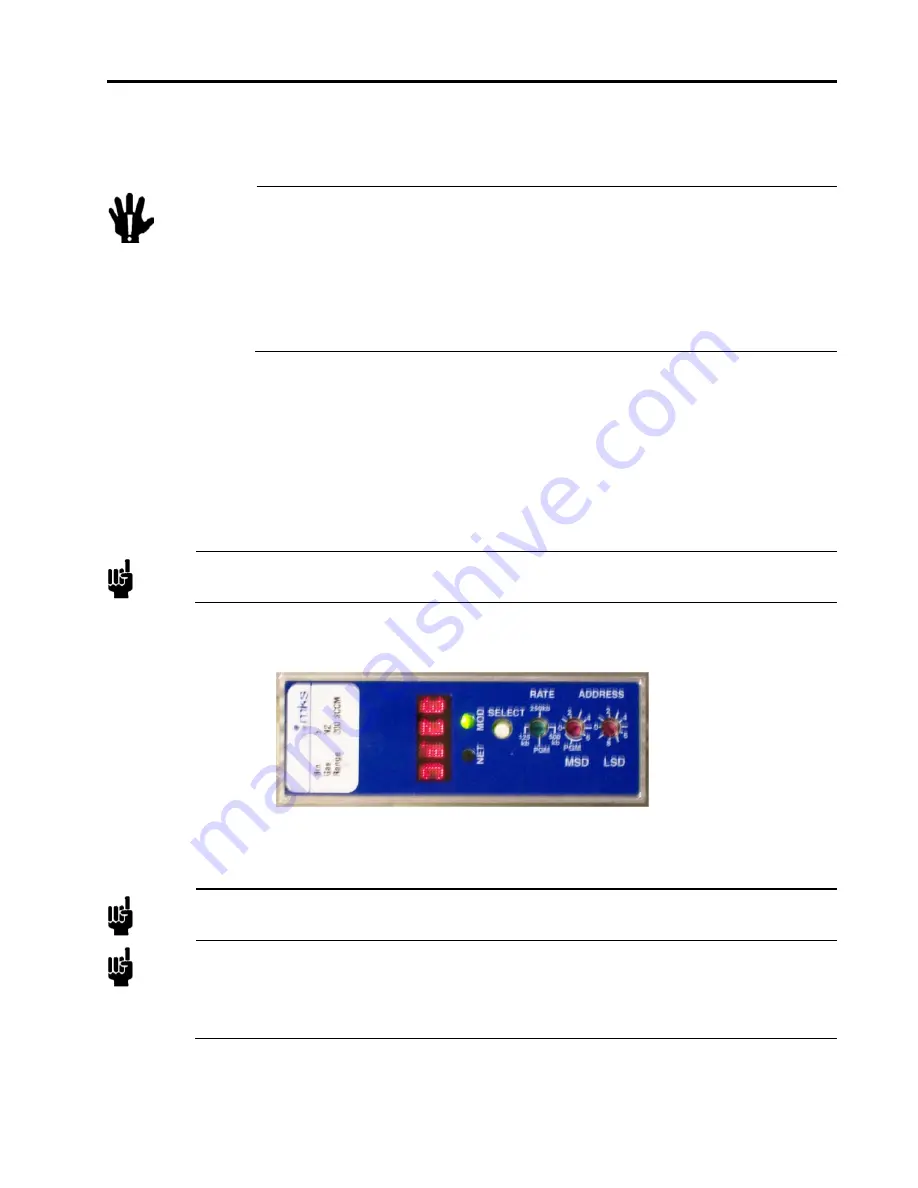
Before installing a Devicenet or an RS485 MFC be sure to set the Baud Rate and MACID for
the device.
Figure 11: Devicenet MAC ID Switches
3.
Perform appropriate helium leak checking of your gas lines and MFC connections to verify the
integrity of the gas seals prior to supplying power to the MFC.
Note
Before connecting the cable leading to the MFC, verify all pinouts for power and signals match
those for the I/O type being used. Information on each I/O type’s pinouts are found Chapter 4.
Note
When using Ethernet interface for setup, a crossover cable (similar to null modem) is required
when the MFC is connected directly to a PC. When the MFC is on a network with a hub
interface, a standard Ethernet cable should be used.
See Chapters 5 and 6 for details on setting up and using the Ethernet user interface.
4.
Connect cable and power up the MFC. Record the IP address, Gas Type and Maximum Flow
Rate (Full Scale Flow Rate) on the calibration sheet.
Содержание P9B
Страница 1: ...1042936 001 Rev A January 2013 MKS Type P9B Digital Mass Flow Controller Instruction Manual...
Страница 4: ......
Страница 10: ...List of References vi This page intentionally left blank...
Страница 20: ......
Страница 22: ...12...
Страница 23: ...13 MKS Instruments Inc MKS Calibration and Service Center...
Страница 24: ...14...
Страница 26: ...16 MKS Instruments Inc MKS MKS Calibration and Service Center...
Страница 27: ...17...
Страница 28: ...18...
Страница 32: ......
Страница 56: ...Chapter Four Analog and Digital Interface Digital Interface Input and Output Options 46...
Страница 64: ......
Страница 68: ...Chapter Five Ethernet Interface Setup and Configuration Digital Interface Input and Output Options 58...
Страница 86: ...Chapter Six Embedded Web Based GUI and Diagnostics Tuning the MFC for Optional PC 76...
Страница 92: ...Chapter Seven Maintenance Pressure Zero Adjustment 82 This page intentionally left blank...
Страница 99: ...Troubleshooting Chart Chapter Eight Troubleshooting 89 This page intentionally left blank...
Страница 100: ......
Страница 105: ...Appendix A Product Specifications Electrical Specifications 95...
Страница 111: ...Model Code Description 101...
Страница 112: ...Model Code Description Appendix C Health and Safety Form 102 Appendix C Health and Safety Form...