2
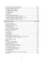
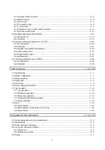
3.6.3 Remote register-based position/speed setting................................................................................ 3 -37
3.7 Function-by-function programming examples........................................................................................ 3 -40
3.7.1 System configuration example......................................................................................................... 3 -40
3.7.2 Reading the servo amplifier status .................................................................................................. 3 -41
3.7.3 Writing the operation commands..................................................................................................... 3 -42
3.7.4 Reading the data .............................................................................................................................. 3 -43
3.7.5 Writing the data ................................................................................................................................ 3 -46
3.7.6 Operation.......................................................................................................................................... 3 -49
3.8 Continuous operation program example................................................................................................ 3 -52
3.8.1 System configuration example when 1 station is occupied ............................................................ 3 -52
3.8.2 Program example when 1 station is occupied ................................................................................ 3 -53
3.8.3 System configuration example when 2 stations are occupied........................................................ 3 -54
3.8.4 Program example when 2 stations are occupied............................................................................ 3 -55
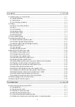
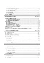
4. SIGNALS AND WIRING
4 - 1 to 4 -46
4.1 Input power supply circuit ........................................................................................................................ 4 - 2
4.2 I/O signal connection diagram ................................................................................................................. 4 - 7
4.3 Explanation of power supply system ....................................................................................................... 4 - 8
4.3.1 Signal explanations ........................................................................................................................... 4 - 8
4.3.2 Power-on sequence .......................................................................................................................... 4 - 9
4.3.3 CNP1, CNP2, CNP3 wiring method ................................................................................................ 4 -11
4.4 Connectors and signal arrangements .................................................................................................... 4 -18
4.5 Signal (device) explanation..................................................................................................................... 4 -19
4.5.1 I/O devices........................................................................................................................................ 4 -19
4.5.2 Input signals ..................................................................................................................................... 4 -22
4.5.3 Output signals................................................................................................................................... 4 -22
4.5.4 Power supply.................................................................................................................................... 4 -23
4.6 Detailed description of signals (devices)................................................................................................ 4 -23
4.6.1 Forward rotation start reverse rotation start temporary stop/restart........................................... 4 -23
4.6.2 Movement finish rough match in position.................................................................................... 4 -24
4.6.3 Torque limit....................................................................................................................................... 4 -26
4.7 Alarm occurrence timing chart................................................................................................................ 4 -27
4.8 Interface................................................................................................................................................... 4 -28
4.8.1 Internal connection diagram ............................................................................................................ 4 -28
4.8.2 Detailed description of interfaces..................................................................................................... 4 -29
4.8.3 Source I/O interfaces ....................................................................................................................... 4 -31
4.9 Treatment of cable shield external conductor ........................................................................................ 4 -32
4.10 Connection of servo amplifier and servo motor ................................................................................... 4 -33
4.10.1 Connection instructions.................................................................................................................. 4 -33
4.10.2 Power supply cable wiring diagrams ............................................................................................. 4 -34
4.11 Servo motor with electromagnetic brake.............................................................................................. 4 -41
4.11.1 Safety precautions ......................................................................................................................... 4 -41
4.11.2 Timing charts.................................................................................................................................. 4 -42
4.11.3 Wiring diagrams (HF-MP series HF-KP series servo motor) ..................................................... 4 -44
4.12 Grounding.............................................................................................................................................. 4 -45
Содержание MELSERVO MR-J3-xT
Страница 22: ...8 MEMO ...
Страница 156: ...4 46 4 SIGNALS AND WIRING MEMO ...
Страница 276: ...7 26 7 MR Configurator MEMO ...
Страница 324: ...10 16 10 SPECIAL ADJUSTMENT FUNCTIONS MEMO ...
Страница 418: ...14 66 14 OPTIONS AND AUXILIARY EQUIPMENT MEMO ...


