3 - 54
3. CC-LINK COMMUNICATION FUNCTIONS
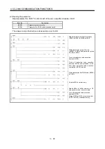
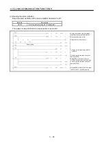
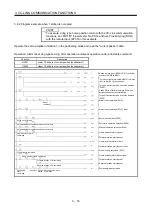
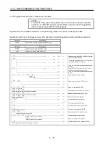
Point table No. selection command (bit0)
Command request time 10ms
Positioning start command reset
Forward rotation start (RY01)
Reverse rotation start (RY02)
Sets monitor code (H01) of current
position (lower 16 bits) to RW
W0
.
Sets monitor code (H02) of current
position (upper 16 bits) to RW
W1
.
Turns on monitor output execution demand
(RY08).
Reads RW
R0
or RW
R1
to D120, D121
of buffer memory when Monitoring
(RX08) turns on.
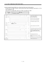
CIRCUIT END
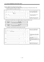
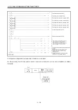
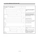
Point table No. selection command (bit1)
Point table No. selection command (bit2)
Point table No. selection command (bit3)
Point table No. selection command (bit4)
Bit 1 selection
Bit 2 selection
Bit 3 selection
Bit 4 selection
Bit 0 selection
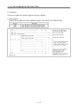
Writes M100 to M131 to remote output
(RY00 to RY2F) of buffer memory.
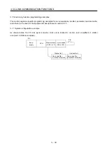
3.8.3 System configuration example when 2 stations are occupied
As shown below, the CC-Link system master local unit is loaded to run one servo amplifiers (2 station
occupied).
Input module
(X20 to X2F)
Master
station
(X/Y00 to 1F)
CPU
Power
supply
PLC
Servo amplifier
(2 station
occupied)
Station No.1
Содержание MELSERVO MR-J3-xT
Страница 22: ...8 MEMO ...
Страница 156: ...4 46 4 SIGNALS AND WIRING MEMO ...
Страница 276: ...7 26 7 MR Configurator MEMO ...
Страница 324: ...10 16 10 SPECIAL ADJUSTMENT FUNCTIONS MEMO ...
Страница 418: ...14 66 14 OPTIONS AND AUXILIARY EQUIPMENT MEMO ...

