


5.
NORME DI MESSA A PUNTO • SET-UP PROCEDURES
ENGLISH
ITALIANO
-
92
-
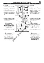
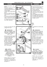
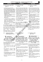
– Disinserire la tensione di alimen-
tazione.
– Posizionare il gruppo sega a 90°
e sollevarlo al massimo.
– Togliere la protezione
A
allentan-
do la maniglia
F
.
– Traslare il carro vagone
H
tutto a
destra.
– Allentare il dado
R
; smontare il
coltello divisore
L
e ribloccare il
dado.
– sollevare verso l'alto il dado
M
e
aprire la protezione
N
; l'apertura
agisce su un micro che impedi-
sce l'aviamento del motore (Ver-
sione USA e CANADA).
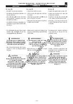
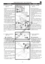
– Inserire il perno
B
nel foro della
puleggia albero sega.
Il dado di bloccaggio C della
lama sega è sinistrorso; per
svitarlo occorre ruotarlo in
senso orario.
– Allentare il dado di bloccaggio
C
con chiave esagonale da 24 mm,
ed estrarre la flangia
D
.
– Togliere il copriforo
Q
.
– Togliere la lama sega
G
.
– Montare il copriforo
P
.
– Montare in sequenza le lame
E
,
la flangia
D
e il dado
C
(per evi-
tare eventuali vibrazioni pulire ac-
curatamente le lame "DADO
SET" e la flangia
D
).
I taglienti G devono essere
posizionati all'interno delle
lame R e ruotati
rispettivamente di 45°.
E' vietato eseguire la
lavorazione senza le lame
esterne R.
– Serrare il dado con la chiave da
24 mm utilizzando il perno
B
.
– Abbassare completamente
l'incisore
O
come descritto nel
paragrafo 5.1.7.
033_060_0.TIF
12
H
N
F
Q
L
G
R
A
M
033_061_0.TIF
13
C
B
O
E
P
D
G
R
– Disconnect input power.
– Position the saw assembly at 90º
and lift it as far as possible.
– Remove protection
A
by
loosening handle
F.
– Translate the wagon
H
.
– Loosen the nut
R
; remove the
dividing knife
L
and block the
nut again.
– Lift the nut
M
upwards and open
the guard
N
; opening activates a
microswitch which prevents the
motor from starting (U.S.A. and
CANADA version).
– Fit pin
B
into the saw shaft pulley
hole.
The locking nut C of the saw
blade is counter-clockwise; to
unscrew it turn it clockwise.
– Loosen the lock nut
C
using a
24 mm hex wrench and remove
flange
D
.
– Remove the hole cover
Q
.
– Remove the saw blade
G.
– Mount the hole cover
P.
– Mount the blades
E
, the flange
D
and the nut
C
in sequence (to
avoid possible vibrations
carefully clean the “DADO SET”
blades and the flange
D
).
The cutters G must be
positioned inside the blades R
and rotated 45
o
respectively.
Machining without external
blades R is prohibited.
– Tighten the nut using the
24 mm wrench and the pin
B
.
– Lower the engraver
O
completely, as described in
paragraph 5.1.7.
www.bricosergio.it