4.
INSTALLAZIONE • INSTALLATION
ENGLISH
ITALIANO
-
72
-
La condizione di lavoro ottimale
per la macchina è quella di fornire
l'esatta tensione riportata sulla
targhetta di identificazione tuttavia
può adeguarsi a tensioni di lavoro
superiori o inferiori in un campo di
tolleranza di +/- 5%.
Al di fuori di questo campo provve-
dere alla regolazione della tensio-
ne di alimentazione.
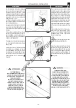
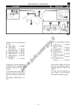
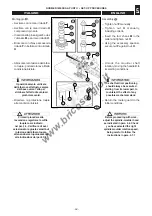
Leggere sulla targhetta di identifi-
cazione macchina (
B
fig.29), il va-
lore della corrente totale assorbita
(Amp.)
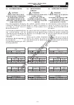
Consultare la tabella di fig. 28 per
usare la giusta sezione di cavi, e
per installare a monte della mac-
china fusibili del tipo "AD INTER-
VENTO RITARDATO"
Predisporre il cavo di alimentazio-
ne in prossimità della morsettiera
A
(fig. 29)
.
Introdurre il cavo all’interno della
morsettiera e collegare le fasi ai
morsetti
R
-
S
-
T
, il neutro (versione
monofase) al morsetto
N
e il cavo
di messa a terra al morsetto con-
trassegnato con il simbolo
(fig.30).
ATTENZIONE AL
COLLEGAMENTO ELETTRICO
L'errata rotazione dell'utensile
causa pericolo all'operatore e
danni al prodotto.
Avviare per una frazione di
secondo il gruppo sega e
verificare che il disco ruoti in
senso orario; nel caso la
rotazione non sia corretta,
togliere immediatamente
tensione ed invertire due delle
tre fasi sui morsetti (R-S-T).
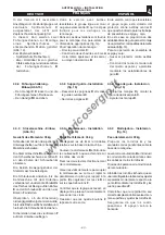
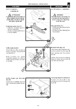
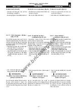
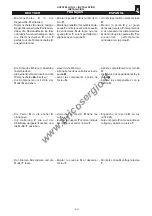
028.031.0.tif
29
•
•
S
•
•
N
•
R
T
63_064_0.tif
30
B
A
The machine works under ideal
conditions when the supplied line
voltage is the same voltage speci-
fied in the machine data plate; how-
ever, higher or lower working
voltage values are also acceptable
within a tolerance range of +/- 5% .
If this tolerance range is exceeded,
input voltage must be corrected.
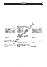
Check total absorbed power (Amp)
in the machine data plate (
B
fig.
29).
Check table fig. 28 to choose ca-
bles having an appropriate cross
section and to install “DELAYED
OPERATION” fuses upstream
from the machine.
Prearrange the feeding cable near
the terminal board
A
(fig. 29).
Drive the cable inside the terminal
board and connect the phases to
the terminals
R
-
S
-
T
, the neutral
wire to the terminal
N
(single-fase
version) and the earthing cable to
the terminal marked by the symbol
(fig. 30).
CAREFUL WITH THE
ELECTRICAL CONNECTION
Incorrect rotation of the tool
causes danger to the operator
and damage to the product.
Activate the saw assembly for a
fraction of a second and check
that the disc turns clockwise.
Should rotation be incorrect,
immediately switch off the power
and invert two of the three
phases on the terminals (R-S-T).
009.072.0.tif
31
www.bricosergio.it


