


5.
NORME DI MESSA A PUNTO • SET-UP PROCEDURES
ENGLISH
ITALIANO
-
104
-
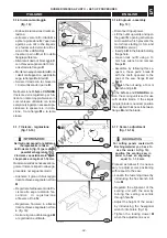
5.4. GUIDA SEGA -
REGOLAZIONE
Il gruppo guida viene utilizzato per
tagli paralleli con sega circolare
e può assumere due posizioni
(fig.25):
A
- per tagli di pezzi di grandi di-
mensioni
B
- per tagli di pezzi bassi e stretti.
Allentare le maniglie
C
per portare
la guida nelle posizioni sopracitate.
Per allontanare o avvicinare la gui-
da alla lama sega operare come
indicato di seguito:
– allentare la leva
F
e il pomello
D
;
– far scorrere manualmente il
gruppo guida
L
facendo riferi-
mento alla riga metrica
E
.
Eseguire la regolazione micro-
metrica procedendo nel seguente
modo:
– bloccare il pomello
D
;
– agire sul pomello
G
per regolare
micrometricamente la guida;
– serrare la leva
F
a registrazione
avvenuta.
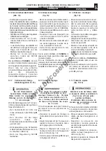
5.5. GUIDA FILO -
REGOLAZIONE
Posizionare la guida filo
A
nella
posizione desiderata e serrare il
pomello
D
.
Per inclinare la guida da 90° a 45°
allentare il bloccaggio
C
e proce-
dere facendo riferimento all'indice
E
.
A regolazione eseguita portare il
fermo guida
P
in battuta sulla gui-
da filo
A
e serrare il pomello
B
.
Le protezioni H e L devono essere
sempre posizionate sull’albero
pialla durante la lavorazione.
5.4. SAW UNIT FENCE -
ADJUSTMENT
The fence unit is used for parallel
cutting with circular saw. It can be
fit into two positions (fig. 25):
A
- for cutting large pieces
B
- to cut low and narrow pieces
Loosen the handles
C
in order to
place the fence in the above
mentioned positions.
To increase or decrease the
distance between the fence and
the saw blade operate as indicated
below:
– release the lever
F
and the
knob
D
;
– manually slide the fence unit
L
with reference to the metric ruler
E
.
Carry out the micrometric
adjustment proceeding as follows:
– lock the knob
D
;
– operate the knob
G
to adjust the
fence micrometrically;
– tighten the lever
F
when the
adjustment has been made
5.5. BUZZ PLANER -
ADJUSTING
Position the planing fence
A
at the
desired point and tighten the knob
D
.
To angle the fence from 90° to 45°
loosen the locking device
C
and
adjust the fence, observing the
value on the index
E
.
As soon as the adjustment has
been carried out, bring the fence
lock
P
to the stop on the surface
unit fence
A
and tighten knob
B
.
During the machining, the
protections H and L must
always be positioned on the
cutterblock.
028.042.0.itf
G
C
F
D
C
G
C
F
D
C
25
A
B
L
L
E
E
028_116_0.tif
C
D
H
26
B
E
A
P
L
www.bricosergio.it