


5.
NORME DI MESSA A PUNTO • SET-UP PROCEDURES
ENGLISH
ITALIANO
-
100
-
Montare allo stesso modo tutti i
coltelli.
A operazione ultimata predisporre
la macchina per la piallatura a filo
o spessore seguendo le indicazio-
ni riportate nel cap. 5 e 6.
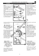
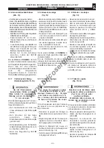
Albero pialla tipo TERSA con 3
coltelli (fig. 21)
– Inserire i coltelli
E
nell'albero
F
attraverso il foro
A
.
– Verificare che i coltelli siano cen-
trati rispetto all’albero pialla
F
.
– Avviare il gruppo operatore pial-
la per bloccare i coltelli.
– Piallare per qualche minuto un
pezzo di legno duro su tutta la
lunghezza dell'albero per otte-
nere un miglior bloccaggio del
gruppo lardone-coltello.
– Per lo smontaggio percuotere il
lardone e sfilare il coltello.
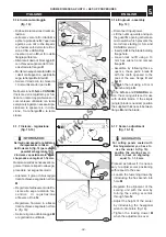
5.2. PIANI A FILO -
REGISTRAZIONE (fig. 22)
Piano d’entrata
Allentare la leva
A
.
Agire sulla maopola
B
per posizio-
nare il piano
D
in funzione del-
l’asportazione desiderata: leggere
lo spostamento sulla targhetta
C
.
A regolazione eseguita serrare la
leva
A
.
Piano d’uscita
Il piano a filo in uscita
E
deve es-
sere perfettamente a filo con i col-
telli montati.
Per verificare il corretto allinea-
mento, posizionare un quadrotto
ben piallato fra piano e albero pial-
la; ruotare manualmente l’albero
pialla e verificare che i coltelli sfio-
rino il quadrotto.
Se si rende necessario un even-
tuale allineamento, allentare la leva
F
e la vite
H
. Allineare il piano
E
agendo sulla manopola
G
.
Serrare la vite
H
e la leva
F
a
regolazione ultimata.
In the same way mount all the
knives.
When the operation has been
completed, set up the machine for
buzz planing or thicknessing
following the instructions in
Chapters 5 and 6.
TERSA-type 3-cutters cutter-
block (fig. 21)
– Insert the knives
E
in the spindle
F
through the hole
A
.
– Check if the knives are centered
with reference to the cutterblock
F
.
– Start the planer working unit to
lock the cutters.
– Take a piece of hard wood and
plane it on its whole length for a
few minutes, in order to get a
better locking of the cutter-gib
unit.
– To remove the cutters, strike the
gib and pull out the cutter.
5.2. SURFACING TABLES -
ADJUSTING (fig. 22)
Inlet table
Loosen the lever
A.
Operate on the handle
B
in order
to place the table
D
depending on
the chosen removal: read the tra-
verse on the data plate
C
.
When the adjustment is over,
tighten the lever
A
.
Outlet table
The outlet surface table
E
must be
perfectly aligned with the mounted
knives.
To make sure it is correct, place a
well planed workpiece between the
surface and the cutterblock;
manually turn the cutterblock and
make sure the cutters skim the
workpiece.
If it is necessary to carry out a
new alignment, loosen the lever
F
and the screw
H.
Get the table
E
aligned by operating the handle
G
.
Tighten the screw
H
and the lever
F
when the adjustment is over.
F
E
E
F
21
030.028.0.tif
A
030.030.0.tif
A
F
H
G
E
B
22
D
C
www.bricosergio.it