


6.
NORME DI FUNZIONAMENTO • OPERATING PROCEDURES
ENGLISH
ITALIANO
-
146
-
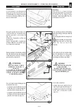
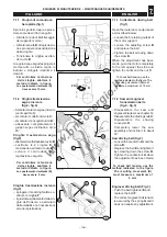
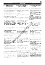
Profilatura con albero inclinato
(fig. 26)
La macchina può essere dotata di
albero inclinabile da 0° a 45°. Que-
sto permette la produzione di profili
diversi utilizzando gli stessi utensi-
li.
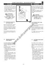
Preparare la macchina alla lavo-
razione nel seguente modo:
– montare la cuffia
G
;
– estrarre, se necessario, gli anel-
li sul piano che impediscono l’in-
clinazione dell’albero;
– montare gli utensili sull’albero
(cap. 5);
La lavorazione con l'albero
inclinato, deve essere eseguita
esclusivamente con utensile di
diametro massimo 150 mm.
– regolare l'altezza e l'inclinazio-
ne dell'albero toupie (cap. 5);
nel caso ci siano interferenze fra
l'utensile e la cuffia
G
, svitare i
pomelli
A
e spostare in avanti la
cuffia toupie nei fori
B
;
– regolare la profondità di lavora-
zione agendo sulle guide toupie
(cap. 5);
Fra la applicazioni pratiche più dif-
fuse troviamo le seguenti:
Inclin45°: profilo della
piattabanda (K) nelle antine.
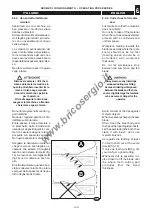
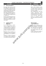
Con albero perpendicolare al pia-
no e con apposito utensile
sagomato
U
(fig.27) si verifica:
– la velocità periferica dell’utensi-
le nel punto
B
è molto maggiore
che nel punto
A
, poiché
R
1
<
R
2
.
Questo potrebbe determinare una
differenza di finitura su tutta la su-
perficie
A
-
B
o anche delle brucia-
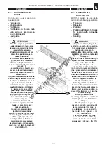
ture. Con albero inclinato a + 45°
(fig.28) tale differenza di finitura
viene minimizzata in quanto
R
1
~
R
2
, utilizzando un opportuno uten-
sile sagomato.
R
1
U
0°
R
2
A
K
B
27
63_071_0.tif
R
1
+ 45°
63_072_0.tif
K
R
2
B
A
258
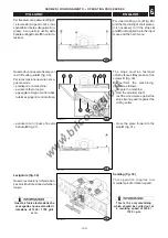
Profiling with tilted shaft
(fig. 26)
The machine can be supplied with
a shaft tilting from 0° to 45°. This
allows machining of different
profiles using the same tools.
Set up the machine in the following
way:
– fit the hood
G
;
– remove if necessary the rings
on the table hindering shaft tilting;
– mount the tools on the shaft (see
chapter 5);
Machining with inclined spindle
must exclusively be carried out
with a tool of maximum 150 mm
diameter.
– Adjust the height and the
inclination of the router spindle
(Chap. 5).
Should there be interference
between the tool and the hood
G
, unscrew the knobs
A
and
move the router hood forward
into the holes
B
.
– adjust working depth using the
moulder fences (see chapter 5.);
The most common practical ap-
plications of this type of profiling are:
+45° tilt: profiling of flitch
(K) in wings.
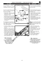
Adjust the shaft so that it is
perpendicular to the table and
using the specially shaped tool
U
(fig. 27) verify that:
– the tool rim speed at point
B
is
much higher than at point
A
,
because
R
1
<
R
2
.
This might lead to a difference in
finishing all over the
A
-
B
surface
or even to burns. When the shaft
is tilted to +45° (fig. 28), this
difference is minimized because
R
1
~
R
2
, if a specially shaped tool
is used.
26
028.106.0.tif
B
B
B
G
A
A
B
www.bricosergio.it