


4.
INSTALLAZIONE • INSTALLATION
ENGLISH
ITALIANO
-
62
-
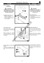
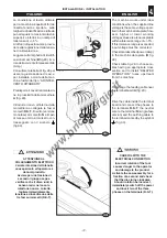
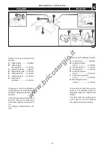
In the version with reversible
stops, the ruler assembly is
equipped with central chip guard
C
which is not indicated for
tenoning work.
In this case two gibs are provided
for mounting an appropriate size
chip guard (fig. 14).
For tenoning operations:
– Remove the chip guard
C
;
– Build two wooden dowels
A
of
the same thickness and tighten
them with the gibs
B
;
4.3.8 Fence support -
Installation (fig. 15)
– Loosen the handles
D
and fit the
sliding fence
C
.
– Tighten the handles
D
.
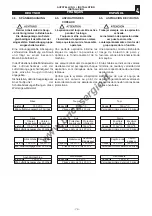
4.3.9
Slotter - Installation
(fig.16)
Weight of the element: 35 kg
Prepare the screws
A
and the re-
lative grommets on the base of
the machine.
Raise the mortiser
B
and fit the
dovetail slide
C
on the heads of
screws
A
.
Secure the two mortiser movement
levers.
Screw down the screws
A
until
joining the mortising machine to
the base and adjust the parallelism
of the table with respect to the bit
E
acting on the screws
D
and on
the four grub screws
F
.
Check proper adjustment by moving
the working table transversally,
and tighten the screws
A
.
Ensure that the four grub screws
F
rest on the base.
Nella versione con battute rever-
sibili, il gruppo riga e' dotato del
paraschegge centrale
C
che non
e' indicato per le lavorazioni di
tenonatura.
In questo caso vengono forniti due
lardoni per il montaggio di un
paraschegge di dimensioni ade-
guate (fig.14)
.
Per l'operazione di tenonatura:
– Togliere il paraschegge
C
;
– Costruire due tasselli di legno
A
dello stesso spessore
e serrarli
tramite i lardoni
B
;
4.3.8 Supporto guida -
Installazione (fig. 15)
– Allentare le maniglie
D
e monta-
re la guida di scorrimento
C
.
– Serrare le maniglie
D
.
4.3.9 Cavatrice -
Installazione (fig. 16)
Peso dell'elemento: 35 kg
Predisporre le viti
A
e relative ron-
delle sul basamento della mac-
china.
Sollevare la cavatrice
B
e inserire
la slitta
C
a coda di rondine sulle
teste delle viti
A
.
Fissare le due leve di
movimentazione della cavatrice.
Avvitare le viti
A
fino ad unire la
cavatrice al basamento e registra-
re il parallelismo del piano rispetto
la punta
E
agendo sulle viti
D
e sui
quattro grani
F
.
Verificare la corretta registrazione
spostando il piano trasversalmen-
te e serrare le viti
A
.
Assicurarsi che i quattro grani
F
siano in appoggio sul basamento.
028.013.0.tif
D
D
C
15
033.008.0.tif
14
A
B
C
028.027.0.tif
D
B
C
16
A
E
F
www.bricosergio.it