4-10
NOTE
z
When the power module has a failure, it may cause problems to other components,
e.g. the monitor suddenly breaks down during start-up, as the power module may
have a power supply protection. In this case, troubleshoot the power module per
the procedure described in the table above.
z
Components of the main unit, SMR and parameter modules are powered by the
power module. In the event that a component malfunctions, check if the operating
voltage is correct. Refer to
2
Theory of Operation
for the operating voltage and
measurement points of each component.
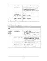
4.6.10 Network Related Problems
Symptoms
Possible Cause
Corrective Action
No connection to LAN
1. Check that network cables and connectors
are in good condition and that the network is
correctly connected.
2. Check that the connectors of the junction
box used to connect the CIS and the patient
monitor are in good condition.
CIS failure
Change the CIS.
The patient monitor
cannot be connected to
a CIS.
DVI interface board
failure
Replace DVI interface board.
Incorrect LAN cable
connection
Check LAN cable connection. LAN cable
shall not be longer than 50 m.
Frequent dropouts and
network disconnects
Incorrect IP address
configuration
Check for IP address conflict. Reconfigure IP
address.
Incorrect LAN cable
connection
Check LAN cable connection. LAN cable
shall not be longer than 50m.
Excessive requests for
viewing the patient
monitor at the same time
A patient monitor can only be viewed by 4
other patient monitors at the same time under
the View Others mode. The excessive view
requests system will be ignored.
Incorrect IP
configuration
Check for IP address conflict. Reconfigure IP
address.
The patient monitor is
connected to a LAN
but cannot view other
patients in the View
Others mode
USB_Hub board failure
Replace the USB_Hub board.
Содержание BeneView T5
Страница 1: ...DPM 6 Patient Monitor Service Manual ...
Страница 2: ......
Страница 4: ...II FOR YOUR NOTES ...
Страница 12: ...6 FOR YOUR NOTES ...
Страница 16: ...1 4 FOR YOUR NOTES ...
Страница 32: ...2 16 FOR YOUR NOTES ...
Страница 68: ...3 36 FOR YOUR NOTES ...
Страница 80: ...4 12 FOR YOUR NOTES ...
Страница 118: ...5 38 4 Remove the module infrared communication backboard and disconnect all the cables from it ...
Страница 124: ...5 44 5 Unscrew the two M3 8 screws on the parameter board Then pull off the parameter board rightward as shown below ...
Страница 126: ...5 46 FOR YOUR NOTES ...
Страница 133: ...6 7 6 3 3 12 1 Screen Assembly with anti glare screen Exploded View ...
Страница 163: ...6 37 6 6 7 BIS Module Exploded View ...
Страница 180: ...6 54 FOR YOUR NOTES ...
Страница 204: ...A 14 FOR YOUR NOTES ...
Страница 205: ......


