4-2
4.4 Software Version Check
Some troubleshooting tasks may require you to identify the configuration and software
version of your patient monitor.
1. To view information on the system configuration and system software version, Select
[
Main Menu
]
→
[
Maintenance>>
]
→
[
Software Version>>
].
2. You can also view the information on system software version and module software
version by selecting [
Main Menu
]
→
[
Maintenance>>
]
→
[
Factory Maintenance>>
]
→
enter the required password
→
[
Software Version>>
].
4.5 Technical Alarm Check
Before troubleshooting the patient monitor, check for technical alarm message. If an alarm
message is presented, eliminate the technical alarm first. For detailed information on
technical alarm message, possible cause and corrective action, refer to the patient monitor’s
Operation Manual.
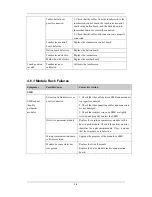
4.6 Troubleshooting Guide
4.6.1 Power On/Off Failures
Symptoms
Possible Cause
Corrective Action
AC mains not connected
or battery too low
Check that AC mains is properly connected or
battery capacity is sufficient.
Power supply protection
Refer to
4.6.9 Power Supply Failures
.
Cables defective or
poorly connected
1. Check that the cables from power switch & LED
board to button board, button board to main board,
and power module to main board are correctly
connected.
2. Check that cables and connectors are not
damaged.
Power switch & LED
board defective
Replace the power switch & LED board.
Power module defective
Replace the power module.
The patient
monitor fails to
start. AC LED
or battery LED
does not light
Mother board Defective
Replace the mother board.
Содержание BeneView T5
Страница 1: ...DPM 6 Patient Monitor Service Manual ...
Страница 2: ......
Страница 4: ...II FOR YOUR NOTES ...
Страница 12: ...6 FOR YOUR NOTES ...
Страница 16: ...1 4 FOR YOUR NOTES ...
Страница 32: ...2 16 FOR YOUR NOTES ...
Страница 68: ...3 36 FOR YOUR NOTES ...
Страница 80: ...4 12 FOR YOUR NOTES ...
Страница 118: ...5 38 4 Remove the module infrared communication backboard and disconnect all the cables from it ...
Страница 124: ...5 44 5 Unscrew the two M3 8 screws on the parameter board Then pull off the parameter board rightward as shown below ...
Страница 126: ...5 46 FOR YOUR NOTES ...
Страница 133: ...6 7 6 3 3 12 1 Screen Assembly with anti glare screen Exploded View ...
Страница 163: ...6 37 6 6 7 BIS Module Exploded View ...
Страница 180: ...6 54 FOR YOUR NOTES ...
Страница 204: ...A 14 FOR YOUR NOTES ...
Страница 205: ......


