3-9
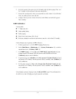
5. Open the relief valve to vent standard CO
2
and make sure that there is an excess gas
flow through the T-shape connector to air..
6. Check the realtime CO
2
value is within 6.0
±
0.3
%
in the
[
Calibrate CO
2
] menu.
Calibration
Tools required:
A steel gas cylinder with 6±0.05% CO
2
and balance gas N
2
T-shape connector
Tubing
Follow this procedure to perform a calibration:
1. Make sure that the sidestream or microstream CO
2
module has been warmed up or
started up.
2. Check the airway for leakage and perform a leakage test as well to make sure the airway
has no leakage.
3. Select
[
Main Menu
]
→
[
Maintenance >>
]
→
[
User Maintenance
>>]
→
enter the
required password
→
[
Maintain CO
2
>>
]
→
[
Calibrate CO
2
>>
].
4. In
the
[
Calibrate CO
2
] menu, select [
Zero
].
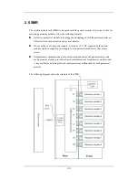
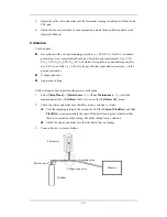
5. After the zero calibration is finished successfully, connect the equipment as follows:
6. Open the relief valve to vent standard CO2 and make sure that there is an excess gas
flow through the T-shape connector to air.
7. In
the
[
Calibrate CO
2
] menu, enter the vented CO
2
concentration in the [
CO
2
] field.
8. In
the
[
Calibrate CO
2
] menu, the measured CO
2
concentration is displayed. After the
measured CO
2
concentration becomes stable, select [
Calibrate CO
2
] to calibrate the
CO
2
module.
If the calibration is finished successfully, the message [
Calibration Completed!
] is
displayed in the [
Calibrate CO
2
] menu. If the calibration failed, the message [
Calibration
Failed!
] is displayed. In this case, perform another calibration.
Monitor
Gas cylinder
Open to the air
Relief valve
Tubing
T-shape connector
Содержание BeneView T5
Страница 1: ...DPM 6 Patient Monitor Service Manual ...
Страница 2: ......
Страница 4: ...II FOR YOUR NOTES ...
Страница 12: ...6 FOR YOUR NOTES ...
Страница 16: ...1 4 FOR YOUR NOTES ...
Страница 32: ...2 16 FOR YOUR NOTES ...
Страница 68: ...3 36 FOR YOUR NOTES ...
Страница 80: ...4 12 FOR YOUR NOTES ...
Страница 118: ...5 38 4 Remove the module infrared communication backboard and disconnect all the cables from it ...
Страница 124: ...5 44 5 Unscrew the two M3 8 screws on the parameter board Then pull off the parameter board rightward as shown below ...
Страница 126: ...5 46 FOR YOUR NOTES ...
Страница 133: ...6 7 6 3 3 12 1 Screen Assembly with anti glare screen Exploded View ...
Страница 163: ...6 37 6 6 7 BIS Module Exploded View ...
Страница 180: ...6 54 FOR YOUR NOTES ...
Страница 204: ...A 14 FOR YOUR NOTES ...
Страница 205: ......


