6-4
6
6802-30-66680
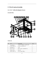
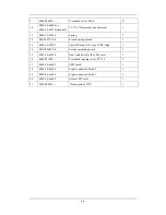
Power switch & LED board
1
7 115-004219-00
Button board
1
8
M04-003105---
Tapping screw PT3×8
3
9
M04-004012---
Crosshead screw M3×6
16
10
6802-30-66901 or
6802-30-66772(optional)
12.1" LCD assembly (anti-glare screen)
1
11 0000-10-10996
Spring
1
12 042-002757-00
Front
housing
bracket
1
13
0000-10-10789
Optical Encoder 16 steps 5VDC Dip6
1
14 042-000693-00
Encoder mounting board
1
15
6802-20-66729
Heat conductor for the LED cover
1
16 M04-051003---
Crosshead
tapping
screw
PT2×6
2
17 6802-30-66682
LED
board
1
18 6802-20-66690
Light
conduction
block
2
1
19 6802-20-66689
Light
conduction
block
1
1
20 6802-20-66688
Alarm
LED
cover
1
21 M6T-040001---
Clamp
spring.1707P
1
Содержание BeneView T5
Страница 1: ...DPM 6 Patient Monitor Service Manual ...
Страница 2: ......
Страница 4: ...II FOR YOUR NOTES ...
Страница 12: ...6 FOR YOUR NOTES ...
Страница 16: ...1 4 FOR YOUR NOTES ...
Страница 32: ...2 16 FOR YOUR NOTES ...
Страница 68: ...3 36 FOR YOUR NOTES ...
Страница 80: ...4 12 FOR YOUR NOTES ...
Страница 118: ...5 38 4 Remove the module infrared communication backboard and disconnect all the cables from it ...
Страница 124: ...5 44 5 Unscrew the two M3 8 screws on the parameter board Then pull off the parameter board rightward as shown below ...
Страница 126: ...5 46 FOR YOUR NOTES ...
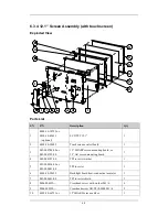
Страница 133: ...6 7 6 3 3 12 1 Screen Assembly with anti glare screen Exploded View ...
Страница 163: ...6 37 6 6 7 BIS Module Exploded View ...
Страница 180: ...6 54 FOR YOUR NOTES ...
Страница 204: ...A 14 FOR YOUR NOTES ...
Страница 205: ......


