3-24
5. Select
[
Respiratory Loop
] in the [
RM Setup
] menu. Verify that the displayed TV is
within 500±50ml and RR is within 20±1rpm.
3.4.14 CCO/SvO
2
Tests
Interconnecting Function
Tools required:
CCO/SvO
2
cable (PN: 115-004083-00)
1. Connect and set the patient monitor and Vigilance monitor per the procedures in the
Operator’s Manual.
2. Set the Vigilance monitor to Demo mode.
3. Check that the CCO/SvO
2
numerics displayed on the patient monitor and Vigilance
monitor are consistent.
Output Performance
Tools required:
Oscillograph (Recommanded model: Agilent DSO5052A)
CCO/SvO
2
cable (PN: 115-004083-00)
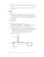
1. Connect the signal output end of the connecting cables of the CCO/SvO
2
module to the
oscillograph.
2. Make the monitor to perform an ECG calibration. Check that the ECG waves displayed
on the oscillograph are consistent with the ECG calibration waves displayed on the
monitor screen.
3. Select
[
CCO Setup
]
→
[
Signal Output Setup >>
] and then select [
Simulated High
Value
] from the pop-up menu. Check that the amplitude of electrical level at the signal
output port of MAP, CVP and SpO
2
are 5±0.25V, 5±0.25V and 10±0.5V respectively.
Содержание BeneView T5
Страница 1: ...DPM 6 Patient Monitor Service Manual ...
Страница 2: ......
Страница 4: ...II FOR YOUR NOTES ...
Страница 12: ...6 FOR YOUR NOTES ...
Страница 16: ...1 4 FOR YOUR NOTES ...
Страница 32: ...2 16 FOR YOUR NOTES ...
Страница 68: ...3 36 FOR YOUR NOTES ...
Страница 80: ...4 12 FOR YOUR NOTES ...
Страница 118: ...5 38 4 Remove the module infrared communication backboard and disconnect all the cables from it ...
Страница 124: ...5 44 5 Unscrew the two M3 8 screws on the parameter board Then pull off the parameter board rightward as shown below ...
Страница 126: ...5 46 FOR YOUR NOTES ...
Страница 133: ...6 7 6 3 3 12 1 Screen Assembly with anti glare screen Exploded View ...
Страница 163: ...6 37 6 6 7 BIS Module Exploded View ...
Страница 180: ...6 54 FOR YOUR NOTES ...
Страница 204: ...A 14 FOR YOUR NOTES ...
Страница 205: ......


