INSTALLATION
25
that have the potential of exciting natural rope
resonance frequencies.
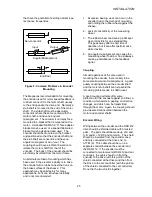
Non-concentric
Input Output
Angular Misalignment
End Float
Figure 5: Common Problems in Encoder
Mounting
The Magnetek recommendation for mounting
the encoder used for motor speed feedback is
to direct connect it to the motor shaft, usually
to the end opposite the drive end. Normally a
stub shaft is mounted in the end of the motor
shaft. The stub shaft must be absolutely
concentric (share the same center) with the
motor shaft, and have no angular
misalignment. The encoder is normally face
mounted to a bracket that is mounted on the
motor. A standard NEMA 56 “C” face adapter
bracket may be used, or a special fabricated
bracket may be designed and used. The
encoder should be mounted on the bracket
and positioned so that the encoder shaft and
the stub shaft are concentric and have no
angular misalignment or run-out. The
coupling should have electrical insulation to
isolate the motor shaft from that of the
encoder. The body of the encoder should be
electrically insulated from the motor frame.
An alternate method of mounting which has
been used in the elevator industry is to drive
the encoder with a rubber wheel that runs on
the brake surface of the sheave. This
approach may be satisfactory for many
applications,
but it can introduce instability
and is not recommended
:
1. Excessive bearing wear can occur in the
encoder due to the method of mounting
and holding the rubber wheel against the
sheave.
2. Lack of concentricity of the measuring
wheel.
3. The rubber wheel can develop a flat spot
when it sits idle for an extended time.
This goes away after a short time of
operation, but it can affect performance
while it exists.
4. An angular misalignment can cause the
measuring wheel to skip or hop sideways,
causing a disturbance in the feedback
signal.
Coupling
Almost regardless of the care used in
mounting the encoder, there is likely to be
some small amount of misalignment. A good
quality coupling between the encoder shaft
and the motor stub shaft can help avoid the
remaining problems due to shaft runout.
A good coupling will also offer some
protection for the encoder against end float, a
condition which exists in gearing on direction
changes, and which can be transmitted
through the motor. Again, the coupling should
provide electrical insulation between the
motor and encoder shafts.
Encoder Wiring
Wiring between the encoder and the DSD 412
drive should be shielded cable with 3 twisted
pairs. The pairs should be made up of A and
A, B and B, +5VDC and common. The shield
should be insulated from the encoder case,
and only connected at the drive end, to
A1TB1(6). This cable should be run in a
separate conduit between the encoder and
the DSD 412. If the encoder must be
connected to two receivers (DSD 412 and car
controller), the cable should run from the
encoder to the drive (with this portion of the
shield connected at the drive) and then from
the Drive to the car controller (with the portion
of the shield connected to the car controller).
Do not tie the two shields together.
Содержание DSD 412
Страница 1: ...DSD 412 DC Elevator Drive Technical Manual CS00407 rev 06...
Страница 6: ...6...
Страница 102: ...MAINTENANCE 102 Figure 24 Connector and E prom Locations...
Страница 103: ...MAINTENANCE 103 Figure 25 Test Point Locations...
Страница 115: ...OUTLINE DRAWING 100A 115 Figure 26 Drive Chassis Outline DSD 412 100 Amp...
Страница 116: ...OUTLINE DRAWING 190A 116 Figure 27 Drive Chassis Outline DSD 412 195 Amp...
Страница 117: ...OUTLINE DRAWING 300A 117 Figure 28 Drive Chasis Outline DSD 412 300 Amp...
Страница 118: ...LAYOUT DRAWING 100A 118 Figure 29 Layout DSD 412 100 Amp A3 A1 A2 A2 L1 NEG GND L2 L3 POS...
Страница 119: ...LAYOUT DRAWING 195A 119 Figure 30 Layout DSD 412 195 Amp A3 A1 A2 A2...
Страница 120: ...LAYOUT DRAWING 300A 120 Figure 31 Layout DSD 412 300 Amp A3 A1 A2 A2...
Страница 121: ......


