MAINTENANCE
111
J15 from the Armature Interface
PCB.
b. Remove the armature voltage
feedback wires at TB5 on the
Armature Interface PCB. Tag these
wires for proper re-assembly.
c. Remove AC input fuses, F1-F3.
d. Remove the (-) DC output lug at top-
left of the drive chassis.
e. Remove the buss bar bolt to the
Current Transducer, at lower right of
the chassis
f. Remove 2 hold-down nuts on the
upper buss-bar.
g. Remove 2 hold-down nuts at the
lower buss-bar.
h. The SCR Power Bridge is now
loose. Remove it by pulling
outward, tilting at the bottom so that
the large tubular resistors cam clear
the fuse mounting bracket.
2. To Reinstall a completely assembled
SCR Power Bridge, follow all of the
above steps in reverse order...and:
a. Use a thin coating of Joint-Al-Z
compound at all electrical buss-bar
to buss-bar interfaces.
b. Use the correct washers nuts and
bolts as were removed for re-
assembly. Start all nut and bolt
hardware before tightening down at
any location.
c. When in proper position,, torque
down the 2 upper and 2 lower buss-
bar mounting nuts to 200 inch-
pounds.
d. Torque down the (-) output lug nut
to 200 inch-pounds.
e. Torque down the bolt at the lower
right buss-bar to xx inch-pounds.
f. Be sure to run PCU diagnostics
when power is re-applied to verify
that all is OK.
Removal and Replacement of the
Armature Interface PCB
1. Remove flat cable connector at J24 and
Current transducer cable at J15.
Remove thermostat and thermistor
connectors at J17, J18 & J20.
2. Tag and remove Armature Voltage
Feedback wires at TB5.
3. Remove 12 pairs of the plug-on SCR
gate and cathode leads.
4. Remove the 3 phase connection nuts at
E31, E32 &E33, near middle of the
PCB. Do not remove the threaded stud.
5. Remove the 6 large nuts at top and
bottom of the PCB.
6. The PCB is now loose. Lift it off from
remaining stud hardware.
7. The Cube ID PCB is located at J19. If
the replacement Armature Interface
PCB does not have a Cube ID PCB in
place, remove it from the old, and place
on to the new.
8. Re-install the replacement Armature
Interface PCB, following steps 1-6
above in reverse order...and:
a. Be sure to re-use all washers and
nuts as originally supplied. These
mechanical ties also make electrical
connections to the PCB.
b. Torque down the small nuts at E31-
33 to 10 inch-pounds.
c. Torque down the larger 6 nuts to 70
inch-pounds.
d. Ensure that the Armature Voltage
Feedback leads at TB5 are re-
connected with the original polarity.
e. Ensure that the proper Cube ID
PCB is installed at J19.
Cooling Fan Replacement
The cooling fan is held in place by 5 socket
head cap screws. These require a 9/64 inch
Allen wrench. The 115VAC supply cord
plugs in from the side. Be sure to move the
fan guard from the old fan to the new unit if
replaced. Retorque mounting screws to 20
inch-pounds.
Thermistor Replacement
The thermistor connects from the heatsink
up to J20 on the Armature Interface PCB.
You must remove the Armature Interface
PCB for access. Trim wires the correct
length to avoid future insulation abrasion
damage. Thermostat switches at J17 & J18
are accessed in the same way.
Current Transducer Replacement
The armature current transducer is mounted
inside the lower right corner of the chassis.
1. Removal:
a. Remove the DC fuse F4.
Содержание DSD 412
Страница 1: ...DSD 412 DC Elevator Drive Technical Manual CS00407 rev 06...
Страница 6: ...6...
Страница 102: ...MAINTENANCE 102 Figure 24 Connector and E prom Locations...
Страница 103: ...MAINTENANCE 103 Figure 25 Test Point Locations...
Страница 115: ...OUTLINE DRAWING 100A 115 Figure 26 Drive Chassis Outline DSD 412 100 Amp...
Страница 116: ...OUTLINE DRAWING 190A 116 Figure 27 Drive Chassis Outline DSD 412 195 Amp...
Страница 117: ...OUTLINE DRAWING 300A 117 Figure 28 Drive Chasis Outline DSD 412 300 Amp...
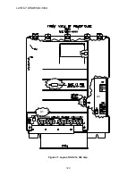
Страница 118: ...LAYOUT DRAWING 100A 118 Figure 29 Layout DSD 412 100 Amp A3 A1 A2 A2 L1 NEG GND L2 L3 POS...
Страница 119: ...LAYOUT DRAWING 195A 119 Figure 30 Layout DSD 412 195 Amp A3 A1 A2 A2...
Страница 120: ...LAYOUT DRAWING 300A 120 Figure 31 Layout DSD 412 300 Amp A3 A1 A2 A2...
Страница 121: ......


