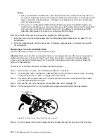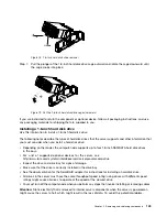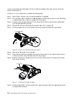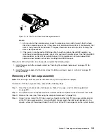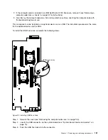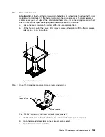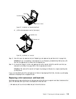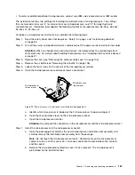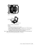
After you install the USB flash drive, complete the following steps:
1. Install the cover onto the compute node (see “Installing the compute node cover” on page 107 for
instructions).
2. Install the compute node into the chassis (see “Installing a compute node in a chassis” on page 93
for instructions).
Removing and replacing Tier 2 CRUs
You may install a Tier 2 CRU yourself or request IBM to install it, at no additional charge, under the type of
warranty service that is designated for your server.
The illustrations in this document might differ slightly from your hardware.
Removing a microprocessor and heat sink
Use this information to remove a microprocessor and heat sink.
• Microprocessors are to be removed only by trained technicians.
Important:
Always use the microprocessor installation tool to remove a microprocessor. Failing to use
the microprocessor installation tool may damage the microprocessor sockets on the system board. Any
damage to the microprocessor sockets may require replacing the system board.
• Be extremely careful, the microprocessor socket contacts are very fragile. Do not touch the
microprocessor socket contacts. Contaminants on the microprocessor contacts or microprocessor socket
contacts, such as oil from your skin, can cause connection failures between the contacts and the socket.
• Do not allow the thermal grease on the microprocessor and heat sink to come in contact with anything.
Contact with any surface can contaminate the thermal grease and the microprocessor socket.
• Do not use any tools or sharp objects to lift the locking levers on the microprocessor socket. Doing so
might result in permanent damage to the system board.
• Each microprocessor socket must always contain either a socket cover or a microprocessor and heat sink.
• Be sure to use only the installation tools provided with the new microprocessor to remove or install
the microprocessor. Do not use any other tool.
• When installing multiple microprocessors, open one microprocessor socket at a time to avoid damaging
other microprocessor socket contacts.
• The microprocessor installation tool has the microprocessor installed on the tool, and may have a
protective cover over the microprocessor. Do not use the tool, or remove the cover until you are
instructed to do so.
Note:
The installation tool has two settings for installing two different sizes of microprocessors. The
settings that are marked on tool are “L” for smaller low core microprocessors, and “H” for larger high core
microprocessors. Installation tool supports the following families of microprocessors: E5-26xx, E5-46xx,
E5-26xx v2, E5-46xx v2.
To remove a microprocessor and heat sink, complete the following steps:
Step 1.
Read the safety information that begins on “Safety” on page v and “Installation guidelines”
on page 89.
Step 2.
Turn off the compute node and peripheral devices and disconnect all power cords.
Step 3.
Remove the cover (see “Removing the compute node cover” on page 105).
Step 4.
Remove the air baffle (see “Removing the air baffle” on page 108).
Step 5.
Locate the microprocessor to be removed (see “System-board internal connectors” on page 15).
162
IBM NeXtScale nx360 M4 Installation and Service Guide
Содержание NeXtScale nx360 M4
Страница 1: ...IBM NeXtScale nx360 M4 Installation and Service Guide Machine Type 5455 ...
Страница 6: ...iv IBM NeXtScale nx360 M4 Installation and Service Guide ...
Страница 34: ...20 IBM NeXtScale nx360 M4 Installation and Service Guide ...
Страница 58: ...44 IBM NeXtScale nx360 M4 Installation and Service Guide ...
Страница 94: ...80 IBM NeXtScale nx360 M4 Installation and Service Guide ...
Страница 192: ...178 IBM NeXtScale nx360 M4 Installation and Service Guide ...
Страница 538: ...524 IBM NeXtScale nx360 M4 Installation and Service Guide ...
Страница 562: ...548 IBM NeXtScale nx360 M4 Installation and Service Guide ...
Страница 722: ......
Страница 730: ......
Страница 737: ......
Страница 738: ...Part Number 00KC216 Printed in China 1P P N 00KC216 1P00KC216 ...

