381298/C
77
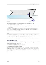
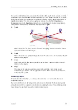
In order to establish a system to measure the relative distance between sensors, a virtual
coordinate system is established. This coordinate system uses three vectors; X, Y and Z.
In the SN90 system, the same vessel coordinate system is used to define the transducer
installation angles. The installation angles are recorded on the SN90
Installation
Parameters
page in the
Installation
dialog box to create the correct sonar presentation
independent of the transducer location and installation angles.
+Y
-Y
+Z
-Z
+X
-X
(CD010101_300_002)
A
B
C
D
+
+
+
A
X-axis
This is the main axis in the vessel’s forward (alongship) direction. Positive values
are forward relative to the origin.
B
Y-axis
This is the transverse (athwartships) direction. Positive values are toward starboard
relative to the origin.
C
Z-axis
This is the vertical direction in parallel with the mast. Positive values are down
relative to the origin.
D
Origo
The origo is the common reference point where all three axis in the vessel
coordinate system meet. All the physical locations of the sensors are referenced
to the reference point.
Installation angles
If you look at the transducer, you can see how it rotates on each axis in the vessel
coordinate system.
Keep in mind that in its default position (all axis set to 0 (zero)) the transducer points
straight down with the orientation mark (arrow) pointing forward. This default position
must always be used as reference for rotation adjustments.
Содержание Simrad SN90
Страница 2: ......
Страница 117: ...381298 C 115 Related topics Installation summary page 65 Installing the transducer ...
Страница 226: ...224 381298 C 427 385 All measurements in mm The drawing is not in scale 385609 Rev B CD12_385609_001_002 Simrad SN90 ...
Страница 236: ...234 381298 C 372915 Clamping frame Simrad SN90 ...
Страница 295: ......
Страница 296: ... 2016Kongsberg Maritime ISBN 978 82 8066 179 1 ...
Страница 297: ......

