381298/C
75
Note
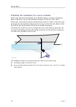
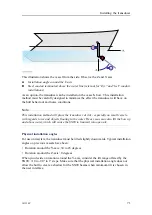
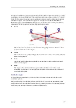
This installation method will place the transducer at risk - especially on small vessels -
with regards to ice and objects floating in the water. Heavy seas may also lift the bow up
and above water, which will cause the SN90 to transmit into open air.
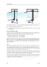
Physical installation angles
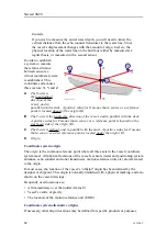
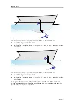
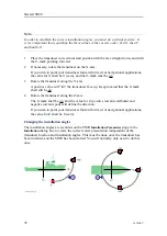
For use as a navigation instrument, the transducer must be tilted slightly downwards.
Typical installation angles on previous vessels have been:
• Rotation around the Y-axis: 60 degrees
• Rotation around the Z-axis: 0 degrees
When you decide on rotation around the Y-axis, consider the tilt range offered by the
SN90: +10 to -90° in 1° steps. Make sure that the physical installation angle does not
allow the hull to create a shadow for the SN90 beams when minimum tilt is chosen in
the user interface.
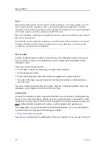
Note
Keep in mind the default "start location" of the transducer; all rotation angles set to 0
(zero) means that the transducer face is horizontal pointing straight down with the
orientation mark (arrow) pointing forward. Lifting the transducer to the requested angle
will always require a positive rotation around the Y-axis.
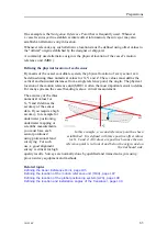
Since the transducer shall point straight forward, the rotation around the Z-axis shall be
kept at 0 (zero) degrees.
You will only need to adjust the rotation around the X-axis if the transducer is mounted
with the orientation mark (arrow) pointing in the wrong direction, or if it necessary
to adjust for an inaccurate installation.
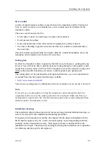
Steel conduit
A total of eight transducer cables are used between the transducer and the Transceiver
Unit. In order to ensure a safe installation, a steel conduit must be installed for the
transducer cables.
There are several reasons for this.
• It will make it easier at a later stage to replace the transducer.
• It will protect the cables.
• Noise and interference from other electrical equipment is greatly reduced.
• The risk of flooding is greatly reduced when the steel conduit is terminated above
the water line.
The steel conduit must preferably be straight. Start the conduit immediately above the
transducer, and terminate it well above the water line.
Содержание Simrad SN90
Страница 2: ......
Страница 117: ...381298 C 115 Related topics Installation summary page 65 Installing the transducer ...
Страница 226: ...224 381298 C 427 385 All measurements in mm The drawing is not in scale 385609 Rev B CD12_385609_001_002 Simrad SN90 ...
Страница 236: ...234 381298 C 372915 Clamping frame Simrad SN90 ...
Страница 295: ......
Страница 296: ... 2016Kongsberg Maritime ISBN 978 82 8066 179 1 ...
Страница 297: ......

