7.11
Section 7
Electrical System and Components
7
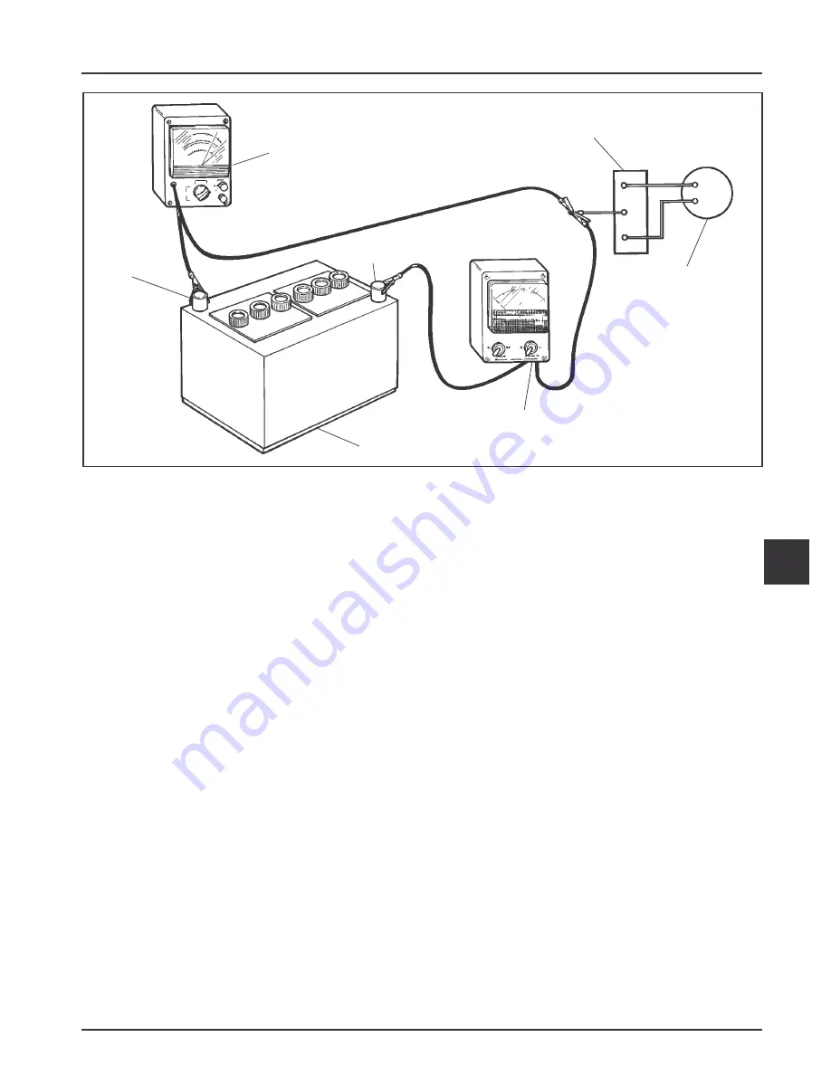
Figure 7-15. Connections for Testing Charging System.
Starter Removal and Installation
Refer to the Disassembly and Reassembly Sections for
starter removal and installation procedures.
Operation – Solenoid Shift Starter
When power is applied to the starter the electric
solenoid moves the drive pinion out onto the drive
shaft and into mesh with the flywheel ring gear.
When the pinion reaches the end of the drive shaft it
rotates the flywheel and cranks the engine.
When the engine starts and the start switch is
released the starter solenoid is deactivated, the drive
lever moves back, and the drive pinion moves out of
mesh with the ring gear into the retracted position.
DC Voltmeter
Rectifier-Regulator
Flywheel
Stator
Ammeter
Battery
(-)
(+)
Electric Starting Motors
The engines in this series use solenoid shift starters. A
Delco-Remy solenoid shift starter is typically used.
Starting Motor Precautions
NOTE
: Do not crank the engine continuously for
more than 10 seconds at a time. If the engine
does not start, allow a 60 second cool-down
period between starting attempts. Failure to
follow these guidelines can burn out the
starter motor.
NOTE
: If the engine develops sufficient speed to
disengage the starter but does not keep
running (a false start), the engine rotation
must be allowed to come to a complete stop
before attempting to restart the engine. If the
starter is engaged while the flywheel is
rotating, the starter pinion and flywheel ring
gear may clash, resulting in damage to the
starter.
NOTE
: If the starter does not crank the engine, shut
off the starter immediately. Do not make
further attempts to start the engine until the
condition is corrected.
NOTE
: Do not drop the starter or strike the starter
frame. Doing so can damage the starter.


