1 Introduction
5
If you have to leave the unit unattended with covers re-
moved during servicing or maintenance, disconnect the unit
from main power supply so that anyone who inadvertantly
touches the unit does not receive an electric shock.
This unit should only be used in areas that are provided with
a protective earth connection to ensure an equipotential
ground connection.
Warning - Explosion hazard
Some disinfectants and cleaning agents may vaporize to
form an explosive vapour. If such disinfectants and cleaning
agents are used the vapour should be allowed to disperse
before switching the unit on.
Warning - Cleaning the unit
Switch the unit off and disconnect it from the main power
supply before cleaning or disinfecting the unit.
The aperture plate and the tube housing are made of lead
(Pb), which is a toxic material. Do not touch it with your bare
hands.
The installer must ensure that:
- The fixing screws are suitable for the wall material.
- The wall for fixing the unit is strong enough for attaching
the unit. It must withstand loads of 5000N or more.
- Pull out strength of the screws is 5000N or more.
- The wall fixing screws are adequately tightened.
To avoid the unit from tipping over, fix the unit with floor
bolts appropriate to the surface the unit is mounted on. The
bolts and the floor material must endure force of 5000 N.
The installer must ensure that the upper shelf attachment
screws are tightened.
The unit should be installed in a place with enough space
for safe operation. See the unit installation manual for rec-
ommended minimum site dimensions. It is the responsibility
of the customer to ensure that the site is large enough for
the patients.
Be aware of hot surfaces when removing covers during in-
stallation and maintenance.
When installing a dental X-ray unit always observe local and
national safety, radiation control and electrical regulations.
Содержание ORTHOPANTOMOGRAPH OP 3D Pro
Страница 1: ...ORTHOPANTOMOGRAPH OP 3D Pro 3D Dental X Ray System Installation Manual ENGLISH 216363 rev 1 0 805 5080...
Страница 2: ......
Страница 4: ......
Страница 8: ...iv rev...
Страница 18: ...1 Introduction 10...
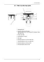
Страница 22: ...2 Unit description 14 Panoramic lights 1 Midsagittal light 2 FH light 1 Image layer 2 TMJ light...
Страница 27: ...2 Unit description 19 2 6 Unit movements Panoramic unit movements R C J D...
Страница 29: ...2 Unit description 21...
Страница 30: ...2 Unit description 22...
Страница 38: ...4 PC requirements 30...
Страница 54: ...5 Installing the unit 46 4 Fasten the covers...
Страница 67: ...5 Installing the unit 59 C C D D Top cover of the column E E...
Страница 104: ...7 Cephalometric calibration and alignment 96...
Страница 111: ...7 Cephalometric calibration and alignment 103 3 Tighten the locking nut...
Страница 117: ...7 Cephalometric calibration and alignment 109...
Страница 128: ...8 Special procedures 120 6 Remove the arm from the column 4 nuts 7 Disassemble the arm...
Страница 132: ...8 Special procedures 124 right handed assembly Prism assembly for the left handed cephalostat...
Страница 158: ...8 Special procedures 150...
Страница 165: ...9 OP 3D Pro Pre sales check list 157 9 11 Notes comments...
Страница 166: ...9 OP 3D Pro Pre sales check list 158 9 12 Dimensions 463...
Страница 167: ...9 OP 3D Pro Pre sales check list 159 9 13 Dimensions with cephalostat...
Страница 168: ...9 OP 3D Pro Pre sales check list 160...

