Detailed Function Description
59
Notice:
z
When running at torque control mode, the acceleration time has nothing to
do with P0.11.
z
The 100% of torque setting is corresponding to 100% of P3.14 (Torque limit).
For example, if torque setting source is keypad (P3.12=1), P3.13=80% and
P3.14=90%, then
Actual torque setting = 80% (P3.13) * 90% (P3.14) = 72%.
6.5 P4 Group --V/F Control
Function
Code
Name
Description
Setting
Range
Factory
Setting
P4.00
V/F
curve
selection
0:Linear curve
1: User-defined curve
2: Torque_stepdown curve (1.3 order)
3: Torque_stepdown curve (1.7 order)
4: Torque_stepdown curve (2.0 order)
0~4 0
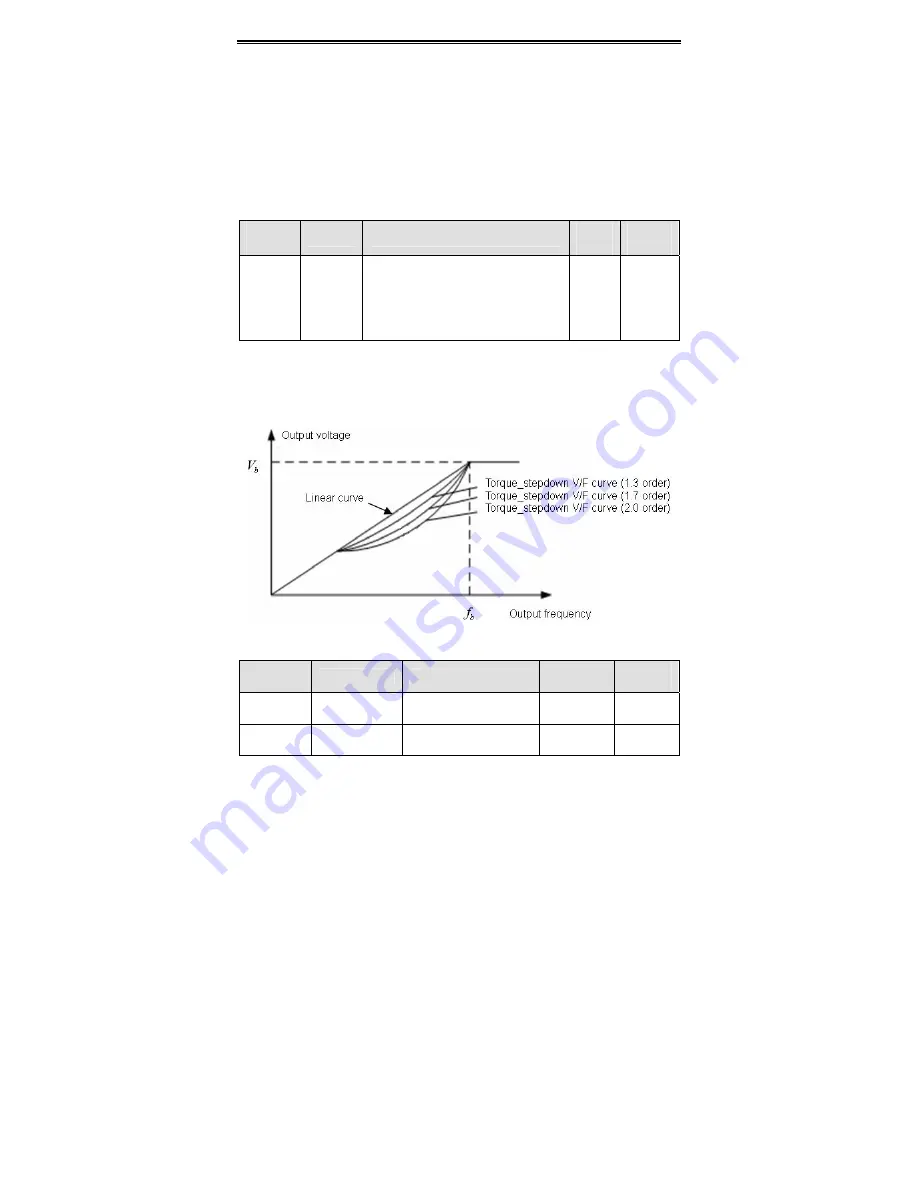
0: Linear curve. It is applicable for normal constant torque load.
1: User-defined curve. It can be defined through setting (P4.03~P4.08).
2~4: Torque_stepdown curve. It is applicable for variable torque load, such as blower,
pump and so on. Please refer to following figure.
Figure 6.10 Multiple V/F curve diagram.
Function
Code
Name
Description
Setting
Range
Factory
Setting
P4.01 Torque
boost
0.0%: auto
0.1
%
~10.0
%
0.0~10.0 1.0
%
P4.02
Torque boost
cut-off
0.0%~50.0% (motor
rated frequency)
0.0~50.0 20.0%
Содержание CHV Series
Страница 2: ......
Страница 12: ...Introduction 4 1 4 Parts Description Figure 1 2 Parts of inverter 15kw and below...
Страница 13: ...Introduction 5 Figure 1 3 Parts of inverters 18 5KW and above...
Страница 23: ...Disassemble and Installation 15 Figure 3 7 Disassembly of metal plate cover Figure 3 8 Open inverter cabinet...
Страница 25: ...Wiring 17 4 1 Connections of Peripheral Devices Figure 4 1 Connections of peripheral devices...


