


Product Overview
Intel® Server Board SE7520BD2 Technical Product Specification
14
Revision
1.3
2.8 Memory
Sub-System
Detail
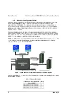
The Server Board SE7520BD2 supports both DDR-1 266MHz and 333MHz memory. For the
server board, there are two DDR-1 channels (channels A and B) from the MCH, each
supporting three DIMM slots. The channels can be configured to operate in dual-channel or
single-channel mode. The MCH chipset requirements dictate that certain memory population
rules have to be followed depending on the type of memory (i.e., 266/333) and the number of
loads per memory channel.
The server board automatically detects the appropriate speed for the memory bus based on
these rules and sets the bus to 266 or 333 MT/s. DDR-1 DIMMs are described as being single
rank (s/r) or dual rank (d/r). To equate loads and DIMM rank, the MCH considers a single rank
DIMM to be one load and a dual rank DIMM to be two loads.
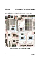
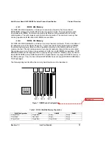
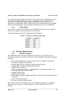
DIMM population starts from the slot that is furthest from the MCH. This is considered to be slot
1. The following high-level block diagram provides a visual representation of the memory
subsystem for the Server Board SE7520BD2.
Figure 6. Intel® Server Board SE7520BD2 Memory/CPU Block Diagram
The following table lists the numbering of the DIMM slots. The silkscreen labels are located next
to each DIMM connector.
Table 2. Memory Bank Labels
Intel® Server Board SE7520BD2
Memory DIMM
Bank
J7B1 (DIMM 3A), J7B2 (DIMM 3B)
3
J7B3 (DIMM 2A), J8B1 (DIMM 2B)
2
J8B2 (DIMM 1A), J8B3 (DIMM 1B)
1