


Error Reporting and Handling
Intel® Server Board SE7520BD2 Technical Product Specification
124
Revision
1.3
5.4.2.5 Processor
Failure
The BIOS detects processor BIST failure and logs this event. The failed processor can be
identified by the first OEM data byte field in the log. For example, if processor 0 fails, the first
OEM data byte will be 0. The BIOS will depend upon BMC to log the watchdog timer reset
event.
If an OS device driver is using the watchdog timer to detect software or hardware failures and
that timer expires, an Asynchronous Reset (ASR) is generated, which is equivalent to a hard
reset. The POST portion of the BIOS can query the BMC for a watchdog reset event as the
system reboots, and log this event to the SEL.
5.4.2.6 Boot
Event
For systems with a BMC, the BIOS downloads the system date and time to the BMC during
POST and logs a boot event. This record does not indicate an error, and software that parses
the event log should treat it as such.
5.4.3 Logging
Format
Conventions
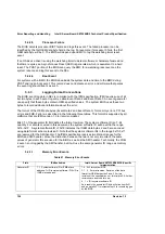
The BIOS event log data in SEL is compliant with the IPMI specification. IPMI requires use of all
but two bytes in each event log entry, called Event Data 2 and Event Data 3. An event generator
can specify that these bytes contain OEM-specified values. The system BIOS uses these two
bytes to record additional information about the error.
The format of the OEM data bytes (Event Data 2 and Event Data 3) for memory errors, PCI bus
errors and FRB-2 errors is described in the following three tables. This format is supported by all
platforms that are IPMI version 1.0 (or later) compliant.
Bits 3:1 of the generator ID field define the format revision. The system software ID is a 7-bit
quantity. For events covered in this document, the system software ID will be within the range
0x18-0x1F. A system software ID of 0x18 indicates that OEM data bytes 2 and 3 are encoded
using data format scheme revision 0. Note that the system software IDs in the range 0x10-0x1f
are reserved for the SMI handler. The IPMI specification reserves two distinct ranges for the
BIOS and SMI handler. Since the distinction between the two is not very important, the same
values of generator IDs are used for the BIOS as well as the SMI handler. Technically, the FRB-
2 event is not logged by the SMI handler, but it will use the same generator ID range as memory
errors.
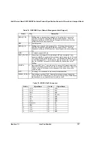
5.4.3.1
Memory Error Events
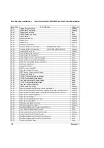
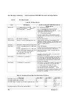
Table 61. Memory Error Events
Field
IPMI definition
Intel® Server Board SE7520BD2 BIOS-Specific
Implementation
Generator ID
7:1 System software ID or IPMB slave
address. 1=ID is system software ID; 0=ID is
IPMB slave address.
7:4 0x3 for system BIOS
3:1 0 Format revision, Revision of the data
format for OEM data bytes 2 and 3, For this
revision of the specification, set this field to 0. All other
revisions are reserved for now.
0 1 = ID is system software ID.
As a result, the generator ID byte will start from 0x31
and go up to 0x3f, in increments of 2 for events logged
by the BIOS.