


Intel® Server Board SE7520BD2 Technical Product SpecificationConnector Pin-outs and Jumper Blocks
Revision 1.3
Intel Confidential
137
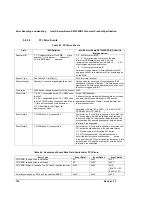
Table 74. OEM RMC 8-pin (Remote Management Card Support)
Name
Pin
Description
SMBUS_SDA
1
SMBus data on baseboard peripheral bus. This allows direct access to
HECETA through the open-drain SMBus v2.0 specification. There is a
baseboard pull-up, and RMC (Remote Management Card) should not be
pulling should not be pulling this up.
GND 2
System
ground
SMBUS_SCL
3
SMBus clock on baseboard peripheral bus. This allows direct access to
HECETA through the open-drain SMBus v2.0 specification. There is a
baseboard pull-up, and RMC should not be pulling should not be pulling this
up.
5VSB
4
5V standby supply <200mA
POST_STATUS 5
Output from Intel chipset BIOS indicating POST has completed. Upon
assertion, mBMC on peripheral bus will cease master transactions. This is a
GPO from ICH and will be a high of 3.3V. It is assumed this meets the VIH
of the OEM input buffer. This is an active high signal, and when this signal is
low, the OEM RMC card should not be issuing any transactions on the
SMBus
PCIRST#
6
Input from RMC card. This is fed into a 5V tolerant AND gate that logically
ORs the front panel reset button into the ICH system reset input. There is a
1Kohm pull-up to 5Vstandby on the baseboard, so an open drain buffer
could be used.
5VCC
7
5V supply <1A max based on pin connector characteristics
POWER_OFF# 8
Power down input from RMC. Asserted low will power down the system.
This is fed into a 5V tolerant gate. There is a 1Kohm pull-up to 5Vstandby on
the baseboard, so an open drain buffer could be used.
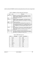
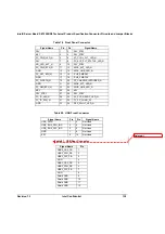
Table 75. EPS12V 2x12 Connector
Pin No.
Signal Name
Pin No.
Signal Name
1 +3.3V
13 +3.3V
2 +3.3V
14 -12V
3 GND
15 GND
4 +5V
16 PS_ON
5 GND
17 GND
6 +5V
18 GND
7 GND
19 GND
8 PWR_GD
20 NC
9 SB5V
21 +5V
10 +12V
22 +5V
11 +12V
23 +5V
12 +3.3V
24 GND