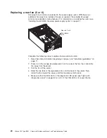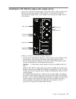
Rear
view
The
following
illustration
shows
the
connectors
and
LEDs
on
the
rear
of
the
server.
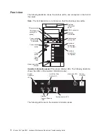
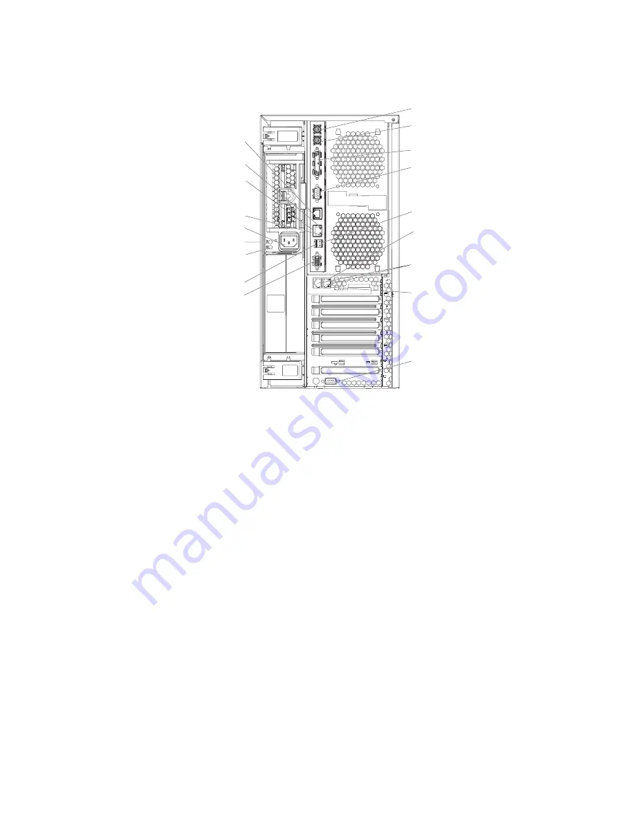
Keyboard connector
Mouse connector
Serial 1 connector
Serial 2 connector
USB 1 connector
ASM
Remote Supervisor
Adapter II
SlimLine Ethernet
Video connector
Ethernet link LED
Ethernet activity LED
Power cord connector
AC power LED
DC power LED
USB 2 connector
Parallel connector
Ethernet link 2
status LED
Ethernet connectors 1 and 2
Ethernet link 1
status LED
PO
WER SUPPL
Y
FILLER
REQ
UIRED FOR
SYSTEM COOLING
WITH EMPTY SLO
T
DO NO
T
THR
O
W
A
W
A
Y
A
TTENTION:
PO
WER SUPPL
Y
FILLER
REQ
UIRED FOR
SYSTEM COOLING
WITH EMPTY SLO
T
DO NO
T
THR
O
W
A
W
A
Y
A
TTENTION:
Keyboard
connector:
Connect
a
PS/2
keyboard
to
this
connector.
Mouse
connector:
Connect
a
mouse
or
other
PS/2
device
to
this
connector.
Parallel
connector:
Connect
a
parallel
device
to
this
connector.
Serial
1
connector:
Connect
a
9-pin
serial
device
to
this
connector.
USB
1
connector:
Connect
a
USB
device
to
this
connector.
Ethernet
link
1
status
LED:
This
LED
is
on
the
Ethernet
connector.
When
this
LED
is
lit,
there
is
an
active
connection
on
the
Ethernet
port
1.
Ethernet
connectors
1
and
2:
Use
these
connectors
to
connect
the
server
to
a
network.
Ethernet
link
2
status
LED:
This
LED
is
on
the
Ethernet
connector.
When
this
LED
is
lit,
there
is
an
active
connection
on
the
Ethernet
port
2.
Serial
2
connector:
Connect
a
9-pin
serial
device
to
this
connector.
Video
connector:
Connect
a
monitor
to
this
connector.
USB
2
connector:
Connect
a
USB
device
to
this
connector.
DC
power
LED:
This
green
LED
provides
status
information
about
the
power
supply.
During
typical
operation,
both
the
ac
and
dc
power
LEDs
are
lit.
For
any
other
combination
of
LEDs,
see
“Light
path
diagnostics”
on
page
93.
6
xSeries
236
Type
8841:
Hardware
Maintenance
Manual
and
Troubleshooting
Guide
Содержание xSeries 236 8841
Страница 1: ...xSeries 236 Type 8841 Hardware Maintenance Manual and Troubleshooting Guide...
Страница 2: ......
Страница 3: ...xSeries 236 Type 8841 Hardware Maintenance Manual and Troubleshooting Guide...
Страница 20: ...10 xSeries 236 Type 8841 Hardware Maintenance Manual and Troubleshooting Guide...
Страница 96: ...86 xSeries 236 Type 8841 Hardware Maintenance Manual and Troubleshooting Guide...
Страница 152: ...142 xSeries 236 Type 8841 Hardware Maintenance Manual and Troubleshooting Guide...
Страница 160: ...150 xSeries 236 Type 8841 Hardware Maintenance Manual and Troubleshooting Guide...
Страница 173: ...Appendix B Safety information 163...
Страница 174: ...164 xSeries 236 Type 8841 Hardware Maintenance Manual and Troubleshooting Guide...
Страница 175: ...Appendix B Safety information 165...
Страница 176: ...166 xSeries 236 Type 8841 Hardware Maintenance Manual and Troubleshooting Guide...
Страница 177: ...Appendix B Safety information 167...
Страница 178: ...168 xSeries 236 Type 8841 Hardware Maintenance Manual and Troubleshooting Guide...
Страница 179: ...Appendix B Safety information 169...
Страница 189: ...Appendix B Safety information 179...
Страница 190: ...180 xSeries 236 Type 8841 Hardware Maintenance Manual and Troubleshooting Guide...
Страница 191: ...Appendix B Safety information 181...
Страница 192: ...182 xSeries 236 Type 8841 Hardware Maintenance Manual and Troubleshooting Guide...
Страница 196: ...186 xSeries 236 Type 8841 Hardware Maintenance Manual and Troubleshooting Guide...
Страница 207: ...W Web site compatible options iv DIMM specification 33 online publications 1 support iv weight 3 Index 197...
Страница 208: ...198 xSeries 236 Type 8841 Hardware Maintenance Manual and Troubleshooting Guide...
Страница 209: ......
Страница 210: ...Part Number 25K8114 1P P N 25K8114...


