background image

Beep Codes


 Beep Codes

One beep and the appearance of text on the monitor indicates
successful completion of POST. More than one beep indicates that
POST detects an error.

Beep codes are sounded in a series of two or three sets of beeps.
The duration of each beep is constant, but the length of the pause
between the beeps varies. For example, a 1–2–4 beep code sounds
like one beep, a pause, two consecutive beeps, another pause, and
four more consecutive beeps.

It is possible to misinterpret a beep code if you do not understand
exactly how they work. Keeping in mind that POST-error beep
codes vary in the length of the pause, and not the duration of the
beep tones, will help you to distinguish the beeps.


Chapter 5. Solving Problems

299

Содержание PC Server 330

Страница 1: ...PC Server 330 User s Handbook IBM...

Страница 2: ...chnical inaccuracies or typographical errors Changes are periodically made to the information herein these changes will be incorporated in new editions of the publication IBM may make improvements and...

Страница 3: ...s 19 Before You Begin 20 Installing Your Software 20 Configuring Your Disk Arrays 25 Maintaining Your Disk Arrays 54 Chapter 3 Configuring Your Server 87 Configuration Overview 89 The Configuration Se...

Страница 4: ...rams 233 Option Diskettes 246 Error Messages 246 SCSI Messages 257 Ethernet Controller Messages 258 ServeRAID Adapter Messages 282 Troubleshooting 288 Beep Codes 299 Checking the System for Damage 303...

Страница 5: ...cord the Identification Numbers 331 Installed Device Records 332 Appendix C Ethernet Cable Specifications 339 10BASE T Cables 339 AUI Cable 341 Appendix D Notices 343 Trademarks 343 Index 345 Contents...

Страница 6: ...vi PC Server 330 User s Handbook...

Страница 7: ...s to devices In the U K by law the power cord must be disconnected after the telephone line cable 2 In the U K by law the telephone cable must be connected after the power cord 1 2 1 Electrical curren...

Страница 8: ...que provenant des c bles d alimentation t lephoniques et de transmission peut pr senter un danger Pour viter tout risque de choc lectrique connectez et d connectez ces c bles comme indiqu ci dessous l...

Страница 9: ...lectrotechnical Commission IEC 825 and CENELEC EN 60 825 for Class 1 laser products When a CD ROM drive is installed note the following CAUTION Use of controls or adjustments or performance of procedu...

Страница 10: ...x PC Server 330 User s Handbook...

Страница 11: ...delete one or more disk arrays Chapter 3 Configuring Your Server describes how to use the Configuration Setup utility program to configure your server This chapter also provides instructions for usin...

Страница 12: ...ovides a description of the cables that you can use to connect the server to an Ethernet IEEE Standard 802 3 network Appendix D Notices contains product notices and trademarks An index follows the app...

Страница 13: ...ontains a parts catalog error codes and advanced diagnostic procedures This manual is intended for trained service technicians Diagnostic diskettes are not included The following pertain to the server...

Страница 14: ...sts who can help you set up install and configure your server 1 The PC Server 330 comes with a limited three year on site warranty In addition IBM s PC Server Startup Support provides coverage to PC S...

Страница 15: ...incorporating various quality standards and design points such as stringent IBM systems assurance testing Refer to the User s Reference for more detailed information on the server features That book...

Страница 16: ...Expansion Bays Hot Swap Server 12 Arranging Your Workspace 14 Comfort 14 Glare and Lighting 15 Air Circulation 15 Electrical Outlets and Cable Lengths 16 Getting Help on the World Wide Web 16 IBM PC S...

Страница 17: ...CI EISA slots Four dedicated EISA slots Expansion Bays Six 5 25 inch drive bays non hot swap server One 5 25 inch and six hot swap drive bays hot swap server Three 3 5 inch drive bays The number of ba...

Страница 18: ...ly used controls and indicators are on the front of your server PC Server 330 Controls Non Hot Swap Server CD ROM Eject Button Power On Light Power Switch CD ROM Drive In Use Light Diskette Eject Butt...

Страница 19: ...cators PC Server 330 Controls Hot Swap Server CD ROM Eject Button Power On Light Power Switch CD ROM Drive In Use Light Diskette Eject Button Diskette Drive In Use Light Chapter 1 Getting Started with...

Страница 20: ...ght damage the information stored on a hard disk or diskette You can configure the server to start at a specified date and time or when it receives a signal from either serial port For more informatio...

Страница 21: ...ghts when your server is accessing a SCSI device If this light remains illuminated this might indicate that either the SCSI bus or the system microprocessor has stopped 2 Secondary Microprocessor In U...

Страница 22: ...Primary Microprocessor Activity Indicator This amber LED blinks to indicate the activity of the microprocessor it also comes on during POST T POST Activity Indicator This amber LED lights while the p...

Страница 23: ...nnector on page 211 Parallel Connector A signal cable for a parallel device such as a printer connects here Serial Connectors Serial signal cables for modems or other serial devices connect here to th...

Страница 24: ...nector The keyboard cable connects here Ethernet Connectors There are two Ethernet connectors A DB 15 and an RJ 45 The DB 15 attachment unit interface AUI connector is for attachment of external 10BAS...

Страница 25: ...on Bays The server has the following expansion bays available Expansion Bays Non Hot Swap Server CD ROM Drive Power On Off Switch Open Bays Open Bays 3 5 Inch Diskette Drive Chapter 1 Getting Started...

Страница 26: ...Expansion Bays Expansion Bays Hot Swap Server CD ROM Drive Power On Off Switch Open Bays 3 5 Inch Diskette Drive Hot Swap Bays 12 PC Server 330 User s Handbook...

Страница 27: ...pported types of drives and their installation see Installing Internal Drives on page 149 CD ROM Drive Your server comes with a SCSI CD ROM drive Diskette Drive The 3 5 inch 1 44 MB MB is approximatel...

Страница 28: ...rence The backrest and seat should adjust independently and provide good support The seat should have a curved front to relieve pressure on the thighs Adjust the seat so that your thighs are parallel...

Страница 29: ...the room lighting changes throughout the day Where it is impossible to avoid reflections or to adjust the lighting an antiglare filter placed over the screen might be helpful However these filters mi...

Страница 30: ...ds refer to the User s Reference Getting Help on the World Wide Web You can access the latest information about product compatibility and configuration on the World Wide Web This information is update...

Страница 31: ...PC Server Startup Support program call the IBM PC Company Automated Fax System at 1 800 426 3395 in the U S or call 1 800 465 3299 in Canada and ask for document number 16125 For more information abo...

Страница 32: ...18 PC Server 330 User s Handbook...

Страница 33: ...ll your operating system This chapter contains Before You Begin 20 Installing Your Software 20 Installing Your Operating System 21 Administration and Monitoring Utility Programs 22 Device Drivers 25 C...

Страница 34: ...tem refer to the README file in Start Here on the ServerGuide Main CD Installing Your Software The ServeRAID adapter can be used with several operating systems With OS 2 Novell NetWare Microsoft Windo...

Страница 35: ...supported by your ServeRAID adapter In the U S call IBM at 1 800 772 2227 In Canada call 1 800 565 3344 In all other countries contact the IBM support organization that services your area your IBM ma...

Страница 36: ...ferent CHANNEL 3 ONL A ONL A ONL B ONL B HSP ONL SBY Adapter 1 Log Drv 0 Log Drv 1 Log Drv 2 Log Drv 3 Log Drv 4 Log Drv 5 Log Drv 6 Log Drv 7 Adapter 2 Adapter 3 Adapter 4 Adapter 5 Adapter 6 Adapter...

Страница 37: ...ide on top of your operating system you can perform tasks such as the following from your active operating system Desktop Select the adapter that you want to monitor View information about the states...

Страница 38: ...llowing Windows environments Windows NT Server Version 3 51 Windows NT Workstation Version 3 51 Windows 95 The Client program includes many of the functions contained in the IBM PC ServeRAID configura...

Страница 39: ...ific type of hardware device They provide instructions that enable the server to interact with the device or to take advantage of a device s special feature The ServeRAID adapter requires the installa...

Страница 40: ...and on the configured hard disk drives If POST does not detect changes in the adapter configuration or an adapter hardware problem continue with step 2 on page 27 If POST detects changes in the adapte...

Страница 41: ...in the system Select a choice using the Up Arrow and Down Arrow keys and press Enter Select Adapter 1 Help 2 ServeRAID Adapter 1 3 ServeRAID Adapter 2 4 Exit IBM PC ServeRAID Adapter Disk Array Config...

Страница 42: ...ess Enter Press Esc to return to previous menu Main Menu 1 Help 2 View Configuration 3 Create Delete Array Log Drive 4 Initialize Synchronize Log Drive 5 Rebuild Device Management 6 Advanced Functions...

Страница 43: ...disk array configuration information Select Create Delete Array Log Drive to select the drives for an array that you want to create or delete This choice also allows you to define and delete logical...

Страница 44: ...n the new physical drive before the state of the logical drive is changed to OKY The rebuild operation is supported only for RAID levels 1 and 5 You also can use this option to define or redefine the...

Страница 45: ...Level Date Created Status WRT Pol A0 A1 A2 B0 B1 C0 C1 1500 1500 1005 1500 3510 1500 1170 RAID 5 RAID 0 RAID 1 RAID 5 RAID 0 RAID 0 RAID 1 03 24 94 03 24 94 03 24 94 03 24 94 03 24 94 03 24 94 03 24...

Страница 46: ...tor You can also attach external devices to a separately purchased cable and then connect the cable from the Internal Channel 2 connector on the adapter and out the back of your server either through...

Страница 47: ...l drive failure FRE The drive is not defined LDM The logical drive is undergoing a RAID level change This state is available only in the remote system of the Administration and Monitoring program OKY...

Страница 48: ...hot Spare or standby hot spare drive enters the Defunct Hot spare DHS state if it fails to respond to the adapter commands EMP No device is present in the bay This state is represented with dashes on...

Страница 49: ...L When the rebuild completes successfully the state changes to ONL The DDD drive is removed from the logical drive and becomes DHS For more information on rebuilding a drive refer to Important Informa...

Страница 50: ...u To make a selection from the Main Menu press the number of the item or use the Up arrow key and Down arrow key to highlight the item and then press Enter Also you can press the Esc key to return to...

Страница 51: ...ID 0 RAID 0 RAID 0 Date Created 12 12 95 12 12 95 12 12 95 Status OKY WT OFL WT OKY WT Ch 2 Ch 1 Bay Array 1 2 3 4 5 6 7 8 9 10 11 12 13 14 15 1 2 3 4 5 6 7 8 9 10 11 12 13 14 15 1 2 3 4 5 6 7 8 9 10...

Страница 52: ...stration and Monitoring program you can add a logical drive to an existing array if the array has free space to create the logical drive You can also create a new array to add additional logical drive...

Страница 53: ...GB or 2 GB they are treated in the disk array configuration as if they all have the same capacity that is the capacity of the smallest disk drive Therefore if you have four drives of 1 GB 1 GB 1 GB an...

Страница 54: ...1 12 13 14 15 Ch 1 Ch 2 Ch 3 CDR Create Delete Array 1 Help 2 Delete Disk Array 3 Create Disk Array 4 Define Logical Drive 5 Define Undefine Hot spare Drive 6 Delete Logical Drive 7 Exit Select a choi...

Страница 55: ...g Logical Drives Create another array now by repeating steps 2 through 5 in this procedure then define logical drives for all arrays Note You must define at least one logical drive for each array crea...

Страница 56: ...Number 1 Bus Number 0 Host ID Null Config 3 Use the Up Arrow key or the Down Arrow key to highlight the array you want to define then press Enter The Select RAID Level pop up window appears and the cu...

Страница 57: ...ONL A ONL B RBL RDY C C 1 Help 2 Delete Disk Array 3 Create Disk Array 4 Define Logical Drive 5 Define Undefine Hot spare Drive 6 Delete Logical Drive Enter a value greater than 2 and less than the d...

Страница 58: ...g in the Logical Drive list might be different from the size you typed The size of a logical drive is determined by a number of factors but basically the size must be divisible by the number of data d...

Страница 59: ...drives among eight disk arrays 7 To define more logical drives repeat steps 1 through 6 of this procedure 8 To leave this screen select Exit or press Esc 9 To ensure that your server operates correct...

Страница 60: ...e Log Drive from the Main Menu then select Synchronize Logical Drive Note Once synchronization starts it cannot be interrupted until the operation is complete Your logical drives are now created and r...

Страница 61: ...ID configuration program refer to Configuring Your Disk Arrays on page 25 2 Select Create Delete Array Log Drive from the Main Menu The following screen appears Bay Bay Array Array Ch 2 Ch 1 Bay Array...

Страница 62: ...e You can press Enter again to toggle between the HSP and RDY state 5 Press Esc when you have finished The cursor will become active in the Create Delete Array Log Drive menu 6 If you want to create a...

Страница 63: ...rive 6 Delete Logical Drive 7 Exit Select a choice using the Up Arrow and Down Arrow keys and press Enter Press Esc to return to previous menu A A ONL ONL B B C C A A ONL ONL B B C C A ONL B A ONL C C...

Страница 64: ...4 for more information If the drive is good set the drive state to Hot Spare HSP then select the drive again and set the drive to Ready RDY If the drive is defective replace it with a good drive then...

Страница 65: ...isk Array 3 Create Disk Array 4 Define Logical Drive 5 Define Undefine Hot spare Drive 6 Delete Logical Drive 7 Exit Select a choice using the Up Arrow and Down Arrow keys and press Enter Press Esc to...

Страница 66: ...logical drive For example if you assigned RAID level 1 to a logical drive and then decided you needed the capacity offered with RAID level 5 you can use this procedure to replace the existing logical...

Страница 67: ...rm pop up window disappears and the cursor becomes active in the menu 5 If you want to define a hot spare drive refer to Setting Device States on page 54 for step by step instructions 6 To create a ne...

Страница 68: ...ation and erasing the device error table This section provides information about the status indicators for logical and hard disk drives and the results of a hard disk drive failure It also contains pr...

Страница 69: ...Adapter Number 1 Bus Number 0 Host ID Null Config 3 Select Set Device State The cursor becomes active in the Bay Array selection list 4 Use the Up Arrow key or the Down Arrow key to highlight the app...

Страница 70: ...nfiguration on page 64 for instructions Results of a Hard Disk Drive Failure Depending on the circumstances a drive failure can result in several possible situations Scenario 1 Only one hard disk driv...

Страница 71: ...rmines the status of the logical drives in the array in which the hard disk is grouped A single hard disk drive failure indicated by a DDD state in the Bay Array selection list generates a CRT state f...

Страница 72: ...check your manufacturers instructions for specific details for detecting a failing hard disk drive Note The LEDs on the SCSI 2 Fast Hot Swap Drive Tray III or the SCSI 2 Fast Wide Hot Swap Drive Tray...

Страница 73: ...n program refer to Starting the Configuration Program on page 25 If the drive failed while the system was powered down a message appears the next time you turn on the system 2 Physically replace the d...

Страница 74: ...st unblock the RAID level 0 drive when the rebuild is complete If you initiated the rebuild through the ServeRAID configuration program and the rebuild was interrupted drives with RAID Level 0 can be...

Страница 75: ...e 25 2 Select Rebuild Device Management from the Main Menu 3 Select Rebuild Drive from the Rebuild Device Management menu The cursor becomes active in the Bay Array list 4 Select the replacement drive...

Страница 76: ...from the Main Menu 3 Select Display Drive Information from the Rebuild Device Management menu The cursor becomes active in the Bay Array selection list 4 Use the Up Arrow key or the Down Arrow key to...

Страница 77: ...rity Error displays the number of parity errors that occurred on the SCSI bus since the Device Error Table was last cleared Misc Error displays the number of other errors such as selection timeout une...

Страница 78: ...ration information in its nonvolatile RAM NVRAM and electrically erasable programmable read only memory EEPROM module The disk array configuration is vital information To protect this information back...

Страница 79: ...use dynamic changes in the configuration of your disk array occur due to hot spare drive replacement or other drive maintenance activity the configuration backup information on the diskette might be d...

Страница 80: ...status is sent after the data is written to the hard disk drive Under certain workloads you can improve performance by changing this write policy to write back WB mode where the completion status is...

Страница 81: ...KY WT OKY WT TAP SHS HSP DHS B RBL RDY ONL DDD ONL ONL ONL ONL ONL ONL ONL ONL ONL IBM PC ServeRAID Adapter Disk Array Configuration Ver 1 XX Adapter Number 1 Bus Number 0 Host ID Null Config 1 Help 2...

Страница 82: ...to move the data from the cache memory to the storage device Failure to follow this practice can result in lost data 7 Press Enter to change the write policy Notice that WT changes to WB You can press...

Страница 83: ...B B C C A ONL B A ONL RDY C C TAP SHS HSP DHS B RBL Advanced Functions 1 Help 2 Backup config to Diskette 3 Restore config from Diskette 4 Change Write Policy 5 Change RAID Parameters 6 IBM RAID Subs...

Страница 84: ...in a moderate to heavily loaded system low rebuild priority will increase the disk rebuild time but provides better system performance Note You can change the rebuild priority without affecting data i...

Страница 85: ...ize reading ahead to the end of the stripe unit will result in lower performance When read ahead is set to Off the size of data transfer from the disk to local cache is equal to the system I O request...

Страница 86: ...function keys in the following order F5 The server continues the startup operation after identifying the drive that is defunct For example a HSP drive failed to respond during POST Startup continues w...

Страница 87: ...Diagnostic 4 Select the diagnostic test that you want to run and press Enter Run Adapter Self Test runs diagnostic tests on the ServeRAID adapter Note Restart your server after the self test is comple...

Страница 88: ...the Configuration Program on page 25 2 Select Advanced Functions from the Main Menu and press Enter 3 Select IBM RAID Subsystem Diagnostics from the Advanced Functions menu Attention A low level forma...

Страница 89: ...82 for more information The Init View Synchronize Configuration menu enables you to view or reset parameters Select a choice using the Up Arrow and Down Arrow keys and press Enter Press Esc to return...

Страница 90: ...started View Unidentified Drive List provides a list of hard disk drives that have an identifier that does not match the stored configuration information The identifier consists of both the configurat...

Страница 91: ...n Arrow keys and press Enter Press Esc to return to previous menu A A ONL ONL B B C C DDD A A ONL ONL B B C C A ONL B ONL A ONL C C TAP SHS HSP DHS B RBL RDY ONL ONL ONL ONL ONL ONL ONL ONL ONL ONL IB...

Страница 92: ...s that are in a RBL or ONL state and are defined in the NVRAM configuration Hard Disk Drive as Source retrieves configuration information from a hard disk drive The configuration information is then c...

Страница 93: ...Mapping 1 Help 2 Display Adapter Status 3 Change Adapter Host SCSI ID 4 Set BIOS Compatability Mapping 5 Set Channel Bank Mapping 6 Exit 1 Extended BIOS Mapping 8GB 2 Limited BIOS Mapping 2GB Select...

Страница 94: ...nk is connected to each of the internal Channels on the ServeRAID adapter This mapping is critical for the correct operation of the Administration and Monitoring program which uses the settings to ide...

Страница 95: ...immediately when the following Mini Configuration prompt screen appears Press Ctrl I for Mini Config Utility Initializing Adapter Number 1 N logical drives are installed NonDisk SCSI Devices Found CDR...

Страница 96: ...splays the current configuration information for the ServeRAID adapter Refer to Viewing the Configuration on page 84 Advanced Functions resets the adapter initializes the configuration and imports the...

Страница 97: ...Flash Pgms 524 Logical Drive with Bad Blocked Stripe Bad Stripe None Blocked Drive None The menu contains the following fields Unattended displays the on off state of Unattended Mode Boot Block Versio...

Страница 98: ...size write policy read ahead status and the date the logical drive was created Press any key to continue IBM PC ServeRAID Adapter Disk Array Mini Configuration Ver 1 XX View Adapter Configuration Inf...

Страница 99: ...tions Reset Adapters Initialize Configuration Import Configuration from Drive s Exit Reset Adapters resets the adapter Attention The following choices may result in loss of data due to changes in the...

Страница 100: ...86 PC Server 330 User s Handbook...

Страница 101: ...s that you install in your server You can use SCSISelect to change default values resolve configuration conflicts and perform a low level format on a SCSI hard disk drive This chapter contains Configu...

Страница 102: ...iguration Conflicts 113 Resolving Software Configuration Conflicts 114 Configuring the Ethernet Controller 115 Using the SCSISelect Utility Program 116 Starting the SCSISelect Utility Program 116 SCSI...

Страница 103: ...t you install in your server the more you will have to interact with your server and your devices to correctly configure your system Your server comes with the following hardware configuration utility...

Страница 104: ...quired to configure your server 1 Run the Configuration Setup utility program and record the current configuration settings 2 Set jumpers or switches on the server s system board See Appendix A Jumper...

Страница 105: ...le for the next system startup while the server is powered off Always run the Configuration Setup utility program if you have added or removed any hardware option or if you receive an error message in...

Страница 106: ...y depending on the BIOS version that comes with your server Using the Configuration Setup Utility Main Menu The Configuration Setup utility program Main Menu lets you select settings you want to chang...

Страница 107: ...the changes and restore the previous settings Select Load Default Settings to cancel the changes and restore the factory settings 6 To exit from the Main Menu select Exit Setup The system prompts you...

Страница 108: ...view the interrupt requests for the Ethernet and SCSI controllers on the system board Devices and I O Ports Software recognizes ports from their port assignments Each port must have a unique port ass...

Страница 109: ...signments for devices or the infrared serial or parallel ports 1 Select Devices and I O Ports 2 Select a device or port use the Left Arrow and Right Arrow keys to advance through the settings availabl...

Страница 110: ...rver to restart following a momentary power loss means that the server is never completely turned off The server must be in the Standby mode off for the Alarm Wakeup Settings features that you define...

Страница 111: ...y on the full Configuration Setup menu Wake Up Timer With this option you can specify a date and time at which the server will be turned on automatically To set the Unattended mode select Alarm Wakeup...

Страница 112: ...ssword User must enter password to complete the system startup Administrator password provides access to all choices on the Configuration Setup utility program menu Administrator and power on password...

Страница 113: ...the password again Attention If an administrator password is set and then forgotten it cannot be overridden or removed You must replace the system board 4 Select Set or Change Administrator Password t...

Страница 114: ...tem Security menu then press Enter The Power on Password menu appears 2 Type the password in the Enter Power on password data field You can use any combination of up to seven characters A Z a z and 0...

Страница 115: ...u then press Enter The Power on Password screen appears 2 Select Password Prompt Press the Left Arrow key or Right Arrow key to toggle the entry to Off Start Options Start options take effect when you...

Страница 116: ...rrow keys to advance through each data field The Advanced Setup choice appears only on the full Configuration Setup menu Cache Control Select this choice to enable or disable the microprocessor cache...

Страница 117: ...s Main Menu then press Enter The system prompts you to confirm your choice If you want to make additional changes you can return to the Configuration Setup Utility If you made any changes and did not...

Страница 118: ...Record the current settings b Install configuration files CFG and overlay files OVL Note If a CFG file did not come with the adapter see Configuration Files on page 109 See Recording EISA Configuratio...

Страница 119: ...tart the backup copy of the EISA Configuration Diskette an introductory screen appears Press Y The Main Menu Steps in configuring your computer appears The EISA Configuration program main menu contain...

Страница 120: ...your configuration or to discard the changes before you exit from the program Use the Up Arrow or Down Arrow key to highlight your selection then press Enter to make your selection To help you track y...

Страница 121: ...teps in configuring your computer appears 4 Use the Up Arrow or Down Arrow key to advance through the items on the screen Use the Tab key to select choices on the bottom of the screen Press the Esc ke...

Страница 122: ...ication mode Maintain SCI files Configuring EISA ISA and PCI Adapters Always use the backup copy of the EISA Configuration Diskette when assigning interrupts for EISA and ISA adapters You cannot assig...

Страница 123: ...iguration utility program See Starting the Configuration Setup Utility Program on page 91 if necessary 3 At the main menu select Step 2 Add or remove boards 4 At the next menu select the slot in which...

Страница 124: ...interact with the device or to take advantage of a device s special feature The device driver might come with the operating system the application program or on the option diskette Not all devices re...

Страница 125: ...Bus Control on page 102 Verify that the IRQ assignments are correct Your PC Server 330 uses a rotational interrupt technique to configure PCI adapters This technique enables you to install a variety...

Страница 126: ...e program is installed that requires the same resource as a hardware device The steps required to resolve a configuration error are determined by the number and variety of hardware devices and softwar...

Страница 127: ...allocations 4 Change adapter jumpers or switches Jumpers and switches define the system resources a device uses If the settings are incorrect or set to use a resource that cannot be shared a conflict...

Страница 128: ...it returns an error Screen messages indicate a conflict exists To resolve conflicts you can change the software or hardware configuration Note Start the Configuration Setup utility program to view th...

Страница 129: ...n The server automatically detects which of the two Ethernet ports is connected to the network and then uses that port for communication This function always active eliminates the need for a media typ...

Страница 130: ...s Use the Up Arrow and Down Arrow key to move the highlight bar to the various menu choices Press Esc to return to the previous menu Also you can press the F5 key to switch between color and monochrom...

Страница 131: ...s for advanced configuration options These options include enabling support large hard disk drives and support for drives with Ultra SCSI speed SCSI Disk Utilities To see the IDs that are assigned to...

Страница 132: ...ure of the SCSISelect Utility program Depending on the hard disk capacity the low level format program could take up to two hours When To Use the Low Level Format Program Use the Low Level Format prog...

Страница 133: ...system serviced 3 To install an operating system after the hard disk drive is formatted refer to the README file in Start Here on the ServerGuide Main CD Saving Configuration Settings When you finish...

Страница 134: ...120 PC Server 330 User s Handbook...

Страница 135: ...ory Module Kits 146 Installing Internal Drives 149 Internal Drive Bays Non Hot Swap Servers 150 Internal Drive Bays Hot Swap Servers 153 SCSI Drives 157 Preinstallation Steps All Bays 162 Installing D...

Страница 136: ...Adding a Hot Swap Storage Expansion Enclosure 222 Adding External SCSI Devices 223 Adding External Options 224 Updating the Server Configuration 225 122 PC Server 330 User s Handbook...

Страница 137: ...you intend to install Place your server in a location that is dry Rain or spilled liquids might damage your server Leave about 51 mm 2 in of space around the front and rear of the server to allow the...

Страница 138: ...your server you must disconnect the telephone line from the server before unplugging any power cords also known as power cables When reassembling your server you must reconnect the telephone line afte...

Страница 139: ...ers the processor board and memory module kits by the edges Never touch any exposed circuitry Prevent others from touching components When you are installing a new option touch the static protective p...

Страница 140: ...ling Static Sensitive Devices on page 125 1 Unlock and open the server door 2 Remove any media diskettes or CDs from the drives and then turn off all attached devices and the server 3 If you have a mo...

Страница 141: ...Remove the front door by carefully lifting it up and off of the hinges Set the door aside 6 Loosen the six screws in the recessed holes on the back of the cover Note The screws stay in place do not at...

Страница 142: ...Preparing to Add Options 9 Remove the cover gently lifting it up as shown 10 Store the cover in a safe place 128 PC Server 330 User s Handbook...

Страница 143: ...Preparing to Add Options 11 Remove the adapter retention bracket Chapter 4 Installing Options 129...

Страница 144: ...Preparing to Add Options Note Perform the next step only if you need to work with the drives or cables in the upper portion of the server 12 Remove the air baffle 130 PC Server 330 User s Handbook...

Страница 145: ...Working with Adapters on page 133 A memory module kit go to Working with Memory Module Kits on page 142 An internal drive go to Installing Internal Drives on page 149 A microprocessor upgrade go to Wo...

Страница 146: ...itional high resolution graphics modes You can increase the memory buffer size to 2 MB by installing two 256 KB by 16 60ns EDO 40 pin SOJ complementary metal oxide semiconductor CMOS dynamic random ac...

Страница 147: ...ons Three types of adapters are available for your PC Server 330 PCI adapters EISA adapters ISA adapters The system board in your server contains three 32 bit EISA ISA bus expansion slots and one PCI...

Страница 148: ...on slots 2 5 are shared slots That is the shared slots use the same expansion slot opening on the back of the server Only one connector in the shared slot pairs can be used at a time Attention To avoi...

Страница 149: ...e Preparing to Add Options on page 126 Remove the server cover see page 127 1 Review the instructions that come with the adapter to determine if the adapter must be installed in a certain slot otherwi...

Страница 150: ...p of the expansion slot cover b Slide the expansion slot cover out of the server c Store it in a safe place for future use 4 Touch the static protective package to any unpainted metal surface on the s...

Страница 151: ...lign the end of the adapter with the card guide on the fan b Press the adapter firmly into the expansion slot c Tighten the expansion slot screw on the top of the adapter bracket 6 Go to Appendix B Se...

Страница 152: ...page 142 An internal drive go to Installing Internal Drives on page 149 A microprocessor upgrade go to Working with Microprocessor Upgrades on page 202 A security option go to Adding Security Options...

Страница 153: ...ernal cables and power cords Remove the server cover see Preparing to Add Options on page 126 1 Note the expansion slot position of the adapter that you want to remove 2 Loosen and remove the screw on...

Страница 154: ...Working with Adapters 5 Insert the adapter you removed into a static protective package Static Devices 6 Install an expansion slot cover in the empty expansion slot 140 PC Server 330 User s Handbook...

Страница 155: ...memory module kit go to Working with Memory Module Kits on page 142 An internal drive go to Installing Internal Drives on page 149 A microprocessor upgrade go to Working with Microprocessor Upgrades...

Страница 156: ...them in adjacent connectors with no vacant memory connectors in between Your server comes with one memory module kit installed in connector J2 the connector closest to the edge of the processor board...

Страница 157: ...Options on page 126 To install a dual inline memory module DIMM 1 Locate the memory connectors on the processor board J2 J3 J4 J5 Notes a Each connector slot contains two keys dividers which are used...

Страница 158: ...5 After aligning the DIMM push the DIMM firmly straight down into the connector The retaining clips on both sides of the connector automatically come up into the notches on the sides of the DIMM Notch...

Страница 159: ...to Installing Internal Drives on page 149 A microprocessor upgrade go to Working with Microprocessor Upgrades on page 202 A security option go to Adding Security Options on page 215 To complete the i...

Страница 160: ...ve a dual inline memory module 1 Locate the memory module kit connectors on the processor board Note the retaining clips at the ends of the connector The clips are used to lock the memory module kits...

Страница 161: ...of the kit size type and speed for future reference Static Devices Note Adding or removing memory module kits changes the configuration information in the server When you restart the server the syste...

Страница 162: ...Where to go next To install or remove An internal drive go to Installing Internal Drives on page 149 A microprocessor upgrade go to Working with Microprocessor Upgrades on page 202 A security option g...

Страница 163: ...ferent types of drives your system can read multiple types of media and store more data Several types of drives are available such as Diskette Hard disk Rewritable optical disc Tape Before you install...

Страница 164: ...disc or tape you might need to remove or change the cover plate Bays 1 6 are for 3 5 inch or 5 25 inch disk drives Bays 1 5 are open bay while bay 6 comes standard with a CD ROM drive The open bays co...

Страница 165: ...h a 7 drop internal SCSI cable depending on the server model that you purchased If you install 16 bit devices you must use the 16 bit cable that comes with your system In some cases you may want to in...

Страница 166: ...ble mediaSee Note 41 3 mm 1 6 inches 6 5 25 inch CD ROM 41 3 mm 1 6 inches 7 3 5 inch Diskette drive 41 3 mm 1 6 inches 8 9 3 5 inch Hard disk diskette or 1 4 inch SCSI tape backup drive 25 4 mm 1 inc...

Страница 167: ...f continuing to operate your system while a hard disk drive is removed or installed These drives are also known as hot swappable drives In these server models you can install up to six hot swappable d...

Страница 168: ...OM drive One of the other two connectors on the three drop cable can be used to connect an additional 3 5 inch device that you install in bay 9 or 10 The Hot Swap Server with RAID comes with an IBM Se...

Страница 169: ...rface devices or 3 5 inch SCSI interface devices such as a hard disk drive or tape backup unit that uses the diskette cable The system board in your server supports a maximum of two diskette interface...

Страница 170: ...ive Height 1 6 3 5 inch Hard disk hot swappable 25 4 mm 1 inch 7 5 25 inch CD ROM 41 3 mm 1 6 inches 8 3 5 inch Diskette 25 4 mm 1 inch 9 10 3 5 inch Hard disk optical disc SCSI diskette 1 4 inch SCSI...

Страница 171: ...rs The hot swap server with RAID also comes with an IBM PC ServeRAID Adapter and two preinstalled SCSI hard disk drives If you install additional SCSI devices you must have a unique identification ID...

Страница 172: ...SCSI devices for information about setting a SCSI ID Table 5 SCSI IDs for Preinstalled SCSI Devices SCSI ID Bay Device Non Hot Swap Servers 6 6 CD ROM Drive 7 N A SCSI 2 Controller Hot Swap Servers wi...

Страница 173: ...use Internal Channel 2 and Internal Channel 3 for connecting internal SCSI devices 2 Internal Channel 3 comes cabled to the backplane 3 Intenral Channel 1 and External Channel 1 cannot be used at the...

Страница 174: ...I Cable Connector on page 211 and Connecting External Options on page 222 in addition to the instructions in this section 2 If you connect devices to the internal or external integrated SCSI connector...

Страница 175: ...ach internal SCSI devices to the SCSI controller in your server you must terminate the last internal device on the bus cable and disable the termination on the other devices connected to the SCSI conn...

Страница 176: ...ore you can install drives in your PC Server 330 you might need to perform certain preinstallation activities Some of the steps are required only during the initial installation of on option 1 Choose...

Страница 177: ...igned the same SCSI ID and are connected to the same channel of the SCSI controller b Automatic SCSI ID settings apply only to hot swappable hard disk drives installed in a hot swap bay Therefore if y...

Страница 178: ...ller If your server did not come with a preinstalled hard disk drive and you plan to have more than seven SCSI drives including the CD ROM drive you might need additional cables If you install 16 bit...

Страница 179: ...t comes with the drives Pay particular attention to the information about setting jumpers and switches and removing termination If a tray is attached to a drive that you intend to install you must rem...

Страница 180: ...emove the screws from the drive housing containing the bottom two bays Note Three screws are shown in the following illustration The fourth screw is located under the housing on the left hand side 166...

Страница 181: ...tention To ensure that the drive functions properly do not overtighten the screws d Attach the drive to the housing using the screws supplied with the drive kit e Connect the drive to one end of the s...

Страница 182: ...at you removed in step 1 on page 166 3 Go to Table 9 on page 333 to record the drive location and if applicable the SCSI ID you assigned to the drive diskette drives do not require a SCSI ID then retu...

Страница 183: ...Optical Disc Drives and Tape Drives on page 200 Removing an diskette drive Go to Removing Diskette Drives on page 170 Removing a hard disk drive Go to Removing Hard Disk Drives Non Hot Swap Servers on...

Страница 184: ...ectrical Safety on page 124 and Handling Static Sensitive Devices on page 125 Removed the server cover see Preparing to Add Options on page 126 Determined the correct location of a failed hard disk if...

Страница 185: ...ontaining the bottom two bays Note Three screws are shown in the following illustration The fourth screw is located under the housing on the left hand side 3 Gently pull the housing away from the brac...

Страница 186: ...t and power from the rear of the drive c Remove the screws that hold the drive in the housing d Slide the drive out of the bay and store it in a safe place 5 Reinstall the drive housing making sure to...

Страница 187: ...re installing another internal drive go to step 1 on page 162 If you are removing another diskette drive return to Removing Diskette Drives on page 170 If you are not installing or removing another in...

Страница 188: ...r Go to Installing Adapters on page 135 Removing an adapter Go to Removing Adapters on page 139 Changing a jumper setting Go to Appendix A Jumpers on page 321 Installing a microprocessor Go to Working...

Страница 189: ...rives If you need additional cables contact your IBM marketing representative or your IBM reseller Note If you install any 8 bit devices you need the 16 bit to 8 bit SCSI Internal Converter To order t...

Страница 190: ...ty on page 124 and Handling Static Sensitive Devices on page 125 Removed the server cover see Preparing to Add Options on page 126 1 Unlock and open the door 2 Remove the door a Lift the door up and o...

Страница 191: ...t panel Save the cover plate for future use 4 Remove the screws that secure the tray from both sides of the tray housing in the target bay as shown in the figure on the next page Then slide the tray o...

Страница 192: ...th the drive into the holes on the tray Then tighten the screws Attention To ensure that the drive functions properly do not overtighten the screws 8 Slide the drive and tray into the target bay 9 Rei...

Страница 193: ...marketing representative or your IBM reseller for additional information a Position the drive with the connectors facing the rear of the server b Slide the drive to the rear until it stops c Loosely r...

Страница 194: ...bit cable to the 16 bit SCSI 2 internal connector 14 Attach one of the 4 pin power cable connectors to the drive 15 If you are installing another internal drive return to step 1 on page 162 If you are...

Страница 195: ...the cover plate at the front of the bay a If you installed a nonremovable media drive use the cover plate that you removed in step 3 on page 177 b If you installed a removable media drive do not inst...

Страница 196: ...Installing Internal Drives 17 Reinstall the door at the front of the server by aligning the pins over the hinges and sliding the door down 18 Close and lock the door 182 PC Server 330 User s Handbook...

Страница 197: ...the drive location and if applicable the SCSI ID you assigned to the drive then return here to determine your next step Note If your server is a disk array model you must configure the disk arrays af...

Страница 198: ...n page 170 Removing a hard disk drive Go to Removing Hard Disk Drives Non Hot Swap Servers on page 190 or Removing Hard Disk Drives Hot Swap Servers on page 195 Changing a jumper setting Go to Appendi...

Страница 199: ...adding additional external devices to your server such as an IBM Enterprise Expansion Tower To do that you would have to use a cable to connect the external storage device to either the external Chan...

Страница 200: ...n Before you remove a defective hot swap drive that is part of an array make sure it is defective If you partially or completely remove a good drive instead of a defective one all of the data in your...

Страница 201: ...sition Open Position b Position the drive tray assembly horizontally with the connector facing the rear of the server c Align the side of the tray with the raised guides on the bottom of the bay d Sli...

Страница 202: ...inates indicating that the drive was installed correctly Light 5 Select the appropriate action from the following list If you are installing another hot swappable drive return to step 4 on page 187 If...

Страница 203: ...g an adapter Go to Removing Adapters on page 139 Removing an diskette drive Go to Removing Diskette Drives on page 170 Removing a hard disk drive Go to Removing Hard Disk Drives Non Hot Swap Servers o...

Страница 204: ...emoving Hard Disk Drives Non Hot Swap Servers To remove a drive from bays 1 5 1 Unlock and open the door 2 Remove the door a Lift the door up and off its hinges b Store the door in a safe place 190 PC...

Страница 205: ...ives 3 Remove the cover plate from the target bay a Insert a small flat blade screwdriver under the side of the cover plate b Lift the cover plate and remove it from the server front panel Chapter 4 I...

Страница 206: ...g a 5 25 inch drive slide the drive out of the bay and store it in a safe place f If you are removing a rewritable optical disc drive also remove the special mounting bracket you installed when you in...

Страница 207: ...the right end of the cover plate into the slots on the right side of the server front panel in front of the newly empty drive bay c Pivot the plate and press it into place 8 Reinstall the door at the...

Страница 208: ...s on page 139 Installing an internal drive Go to Installing Internal Drives on page 149 Changing a jumper setting Go to Appendix A Jumpers on page 321 Installing a microprocessor Go to Working with Mi...

Страница 209: ...mpt to remove a defective drive thoroughly review the information displayed on your server screen to determine the location of the failed drive Logical and Hard Disk Drive Status Indications on page 5...

Страница 210: ...IBM reseller or IBM marketing representative to purchase the types of drive trays that you need Green Amber Description On Off Drive tray is powered on the hard disk drive is inactive and the drive sh...

Страница 211: ...b to the right b Pull the tab outward 3 Identify the drive that you want to remove If your server is a hot swap server and a hard disk drive has failed ensure that you have selected the correct drive...

Страница 212: ...the connector on the backplane by grasping the handle on the tray and pulling the drive out of the server Store the drive in a safe place Note If your server is a disk array model you may need to reco...

Страница 213: ...swappable drive close the interior door and then continue with the next step 7 Update your records in Table 9 on page 333 then return here to determine your next step Where to go next To install or re...

Страница 214: ...tall 16 bit devices you must use a 16 bit cable To connect an 8 bit device to a 16 bit cable you must purchase and use the 8 bit to 16 bit SCSI Internal Converter The CD ROM drive in your server comes...

Страница 215: ...odule Kits on page 142 Installing an adapter Go to Installing Adapters on page 135 Removing an adapter Go to Removing Adapters on page 139 Removing an diskette drive Go to Removing Diskette Drives on...

Страница 216: ...rements be sure to use the VRM that comes with the microprocessor Before you begin Read Electrical Safety on page 124 and Handling Static Sensitive Devices on page 125 Read the instructions that came...

Страница 217: ...s section might differ slightly from your hardware 2 To avoid damage and ensure proper server operation when you install a new or additional microprocessor use the same speed and voltage requirements...

Страница 218: ...void getting a burn while removing an existing microprocessor or installing an additional one if you let the components cool for 10 minutes before continuing with the procedures described in this sect...

Страница 219: ...Pin 1 location 5 Microprocessor 6 Fan power cable connector J21 7 Secondary processor board socket empty with lever in closed locked position 8 Primary processor board socket with lever in closed pos...

Страница 220: ...sor and while installing the microprocessor and the fan sink 3 Touch the static protective package containing the new microprocessor to any unpainted metal surface on the server then remove the microp...

Страница 221: ...gn the pins with the corresponding holes on the socket 10 Carefully insert the microprocessor into the socket Ensure that the pins on the microprocessor align with the holes in the socket Attention Do...

Страница 222: ...ressing gently on the top of the arched side of the clip Power Connector Flanges 14 Press on the arched legs of the clips until each snaps over the flange 15 Attach the smaller connector on the power...

Страница 223: ...or the location of the fan connector 17 Install the voltage regulator module VRM in the secondary VRM connector a Position the VRM above the processor board connector as shown in the illustration b Pr...

Страница 224: ...If your operating system does support SMP refer to your operating system documentation You might need to make changes so that the operating system recognizes the new microprocessor Where to go next To...

Страница 225: ...you install the SCSI cable you must connect a terminator or a properly terminated SCSI device to the external connector In this procedure you will remove the SCSI knockout panel Two narrow metal stri...

Страница 226: ...the screws from the connector end of the external SCSI cable Set the screws aside b Insert the other end of the cable to the external SCSI connector on the system board c Insert the connector end of...

Страница 227: ...owing a Remove the screws from the connector end of the external SCSI cable Set the screws aside b Insert the other end of the cable to the RAID adapter c Insert the connector end of the cable through...

Страница 228: ...al SCSI Cable Connector 7 Insert the screws through the holes on the cable connector then tighten the screws 8 Complete the installation see Completing the Installation on page 218 214 PC Server 330 U...

Страница 229: ...the rear of your server Before you begin Obtain the following A flat blade screwdriver An adjustable wrench A 19 mm 3 4 in U bolt or wire rope similar to National Manufacturing No 3230 Stock No 176 7...

Страница 230: ...U bolt through the holes and secure it in place with the nuts 2 Thread the cable through the U bolt and around an object from which it cannot be removed then fasten the cable ends together with a loc...

Страница 231: ...dditional security you might want to control access to the cables and cable connectors on your server The optional PC Server Security Cover restricts cable access while creating a sleek streamlined pr...

Страница 232: ...tallation Completing the Installation Before you begin Complete all the installation procedures for the options you have chosen to install 1 Reinstall the air baffle if you removed it 218 PC Server 33...

Страница 233: ...Completing the Installation 2 Reinstall the adapter retention bracket Slot Chapter 4 Installing Options 219...

Страница 234: ...e the cover in place b Tighten the six screws in the recessed holes on the cover Captive Screws 4 Close and lock the server door if you haven t done that yet Attention Be sure to maintain a clearance...

Страница 235: ...eyboard Mouse Serial Devices Monitor Parallel Device Power Cords 6 If you have a modem or fax machine attached to the server reconnect the telephone line to the wall outlet and the server Where to go...

Страница 236: ...ructions that come with the option to prepare it for installation Adding a Hot Swap Storage Expansion Enclosure The IBM PC Server Enterprise Expansion Enclosure is one of several SCSI storage enclosur...

Страница 237: ...mination jumper J38 See Appendix A Jumpers on page 321 for more information If you plan to install external SCSI devices you must order an additional SCSI cable That is to use external devices with th...

Страница 238: ...onnector Serial Connectors Infrared Connector Expansion Slots Ethernet Connectors Keyboard Connector Mouse Connector Monitor Connector Where to go next Device drivers to install See the instructions t...

Страница 239: ...he documentation that comes with your option for information about installing any required device drivers Notes 1 If you remove a SCSI device the server might not recognize any SCSI devices that are s...

Страница 240: ...Updating the Server Configuration 226 PC Server 330 User s Handbook...

Страница 241: ...Codes 230 Test Programs 230 Types of Error Messages 231 Troubleshooting 232 Option Diskettes 233 About the Test Programs 233 Using the PC Server Diagnostic Diskette 233 Using the Main Menu 234 Program...

Страница 242: ...ng Other Network Adapters 296 Beep Codes 299 Checking the System for Damage 303 After Dropping It 303 After Spilling Liquid on It 304 Installing Additional Test Programs 305 Using the Utility Programs...

Страница 243: ...sts to check the operation of the system and some options This series of tests is called the power on self test or POST POST does the following Checks some basic system board operations Checks the mem...

Страница 244: ...es that POST detected an error For more information on beep codes see Beep Codes on page 299 Test Programs The PC Server Diagnostic Diskette contains the QAPlus PRO test programs developed by DiagSoft...

Страница 245: ...usage device drivers and so on Utility Programs The utility programs include a text editor and a diskette formatter Types of Error Messages Error messages indicate that a problem exists they are not...

Страница 246: ...device failed its test 2 or higher The test stopped Software Generated Error Messages These messages appear if a problem or conflict is found by an application program the operating system or both Fo...

Страница 247: ...est the IBM PC Server 330 Non IBM products tested with these programs might present misleading error messages or unexpected system responses If you want to test a non IBM product refer to the informat...

Страница 248: ...continue Pressing any key then returns you to the Diagnostics Menu Module Tests more rigorously test an individual module or device such as a diskette drive or specify a group of tests for several mo...

Страница 249: ...s choice from the Main Menu the Utilities Menu appears The Utilities Menu provides access to additional programs on the Diagnostic Diskette These utility programs include RAM Chip Locator File Editor...

Страница 250: ...down Up Arrow Moves the cursor up F1 Displays the appropriate Help information Use the Up Arrow or Down Arrow key to scroll through the information Pressing F1 from within a Help screen provides a hel...

Страница 251: ...Memory Displays next logical unit number only used in the Test Module menu and Test Group screens Displays previous logical unit number only used in the Test Module menu and Test Group screens Using...

Страница 252: ...o include These options are helpful if you have insufficient memory available to load all of the test programs simultaneously or if you want to test specific test groups The valid test groups are LPT...

Страница 253: ...as the command line switch IntruderAlert When you run the diagnostic programs IntruderAlert checks for damage to the Diagnostic Diskette If a virus or program alteration is detected the diagnostic pr...

Страница 254: ...ated test group The following illustration is an example of the Test Group Window when the system board is selected from the Module Tests Menu QAPlus PRO for PC Server v 5 20 F1 Help F2 Log F10 Local...

Страница 255: ...or off When you have selected a test a diamond appears next to the selection Attention An asterisk directly adjacent to an item indicates that running that test might damage your data Make sure to bac...

Страница 256: ...ess Enter Creating Test Scripts Scripting allows you to select specific groups of tests testing parameters and options You can then save your selections for later use as a test script To set up a test...

Страница 257: ...dividual test basis Therefore if you select tests A B and C and the Lap Count is set to 3 the test sequence is ABC ABC ABC Pause Control You can have the test programs pause between test modules and w...

Страница 258: ...the Test Log file The test programs automatically assign the extension LOG to the file if you do not specify a file name extension The file is stored in ASCII text format You can then examine the file...

Страница 259: ...er This diagnostic diskette includes the LANAID utility program Backing Up the Ethernet Diagnostic Diskette Use an operating system command such as the DOS DISKCOPY command to make a complete backup c...

Страница 260: ...ror messages POST error messages appear when during startup POST finds problems with the hardware or detects a change in the hardware configuration Diagnostic error messages appear when the diagnostic...

Страница 261: ...ing Your Server 2 If a password prompt appears with a POST message type the administrator or power on password then press Enter POST Message Description E100 E101 POST detected an invalid EISA configu...

Страница 262: ...A device has been removed or disconnected from a cable A device is failing and is no longer recognized by the server as being installed An external device is not turned on An invalid checksum is detec...

Страница 263: ...sing the VPD Action Have the system serviced 175 A hardware error occurred Action Have the system serviced 176 The server cover has been removed improperly Action Check for indications that the server...

Страница 264: ...ion Setup Utility Main Menu 186 A system board or hardware error occurred Action Have the system serviced 187 VPD serial number not set 1804 Action Have the system serviced 188 System ID information d...

Страница 265: ...ou have just connected a new mouse or other pointing device turn the server off and disconnect that device Wait at least 5 seconds and then turn the server on If the error message goes away replace th...

Страница 266: ...other serial device attached to your server verify that the serial cable is connected correctly If it is use the following procedure 1 Turn off the server 2 Disconnect the serial cable from the seria...

Страница 267: ...outing 1801 A PCI adapter has requested memory resources that are not available Action 1 Make sure the PCI adapter and all other adapters are set correctly in the configuration programs If the memory...

Страница 268: ...page 133 1805 A PCI adapter ROM error occurred Action Remove the PCI adapters If you can start the system without the adapters reinstall each adapter and retest When an option fails replace it If you...

Страница 269: ...er 3 Turn on the server If the POST error message does not reappear the pointing device is probably failing See the documentation that comes with the pointing device for additional testing information...

Страница 270: ...Error Messages POST Message Description Other Numbers The POST found an error Action Follow the instructions on the screen 256 PC Server 330 User s Handbook...

Страница 271: ...n improperly installed cable A defective cable Action Verify that The external SCSI devices are turned on External SCSI devices must be turned on before the system The cables for all external SCSI dev...

Страница 272: ...lay messages from the following drivers Novell NetWare Server ODI Novell NetWare Server DOS ODI Novell NetWare Server OS 2 ODI Novell NetWare Server LAN NDIS Adapter for level 2 01 NDIS Adapter for le...

Страница 273: ...tion command Explanation The IRQ setting might be incorrect with the hardware setting or the EEPROM might be corrupted Action Perform the following steps 1 Verify that the IRQ settings in the NET CFG...

Страница 274: ...Routing on page 94 for more information PCNTNW NW 075 The MLID cannot be registered with the LSL Explanation An error occurred while the driver was trying to register with Link Support Layer Action C...

Страница 275: ...eter block is too small Explanation The driver parameter block is too small Action Restart the server If the error recurs call for service PCNTNW NW 087 The media parameter block is too small Explanat...

Страница 276: ...he IEEE address has a group bit indicating that an address belongs to a group of stations This bit is used only as a destination address it cannot be used as a source address You tried to enter a sour...

Страница 277: ...planation The Ethernet controller does not require a DMA setting Action Delete the DMA parameter from the NET CFG file Novell NetWare DOS ODI Driver Messages This section contains the error messages f...

Страница 278: ...esident PCNTNW MLID from memory and failed A hardware error has probably occurred Action Run the Ethernet diagnostic PCNTW DOS 6 The adapter did not initialize PCNTNW did not unload Explanation The ha...

Страница 279: ...NTNW DOS 11 The MLID does not support frame string The PROTOCOL keyword has been ignored Explanation The NET CFG files specified the PROTOCOL option for a PCNTNW MLID The specified frame type is not s...

Страница 280: ...st address byte is a 1 This bit must always be 0 For example if the first byte has the following address an invalid Ethernet address is generated FIRST BYTE 7 6 5 4 3 2 1 0 0 0 0 0 0 0 0 1 This byte w...

Страница 281: ...on page 233 to run the diagnostic utility PCNTNW DOS 54 The board did not respond to the initialization command Explanation The Ethernet controller initialization failed Action Verify that the Etherne...

Страница 282: ...locate the Ethernet contoller on the PCI bus Action Perform the following steps 1 Verify that the Ethernet enable jumper is set to the default enable position 2 Use the BUSTYPE keyword to specify a v...

Страница 283: ...itialization command Explanation The board initialization failed Action Verify that the Ethernet enable jumper is set to the default enable position Go to About the Test Programs on page 233 to run th...

Страница 284: ...NET CFG file Action Verify that the IO address in NET CFG matches with the board Otherwise remove the PORT keyword from the NET CFG file PCNTNW OS2 67 PCI scan specified device not found Explanation...

Страница 285: ...ND DOS 7 Protocol Manager device error Explanation The NDIS stack is not configured properly Action Check and correct your configuration PCNTND DOS 8 Bad status for Protocol Manager Explanation The ND...

Страница 286: ...est Please run configuration utility Explanation The driver cannot find an Ethernet controller Action Perform the following steps 1 Verify that the Ethernet enable jumper is set to the default enable...

Страница 287: ...PROTOCOL INI PCNTNW DOS 32 IRQ number is already in use by another PCNET device Explanation The specified IRQ number is already in use by another Ethernet controller or device Action Modify the IRQ s...

Страница 288: ...already in use by another device Explanation The specified IRQ is specified by another device Action Modify the IRQ setting in the setup dialog box PCNTN3 18 PCI scan specified device not found Explan...

Страница 289: ...correct syntax If the command is in the AUTOEXEC NET file edit the file to correct the syntax The only parameters that should be included are PCNTPK and BUSTYPE PCI1 PCNTPK DOS 2 Unable to reset the P...

Страница 290: ...1 Verify that the Ethernet enable jumper is set to the default enable position 2 Go to About the Test Programs on page 233 to run the diagnostic utility PCNTPK DOS 8 INT packet_int_no should be in th...

Страница 291: ...Programs on page 233 to run the diagnostic utility Packet driver is at segment xxxx Explanation The memory address where the packet driver is loaded is xxxx Action None Packet interrupt number xxxx E...

Страница 292: ...e system is out of Streams memory blocks Action Use the CRASH utility to increase the number of Streams memory blocks for the failing size another Ethernet controller Action Modify the IRQ settings in...

Страница 293: ...on The IRQ specified or found conflicts with other devices in the system Action Perform the following steps 1 Modify your hardware settings 2 Run netconfig to match the hardware settings pnt0 14 Canno...

Страница 294: ...iver found in the system Action Ignore this message if you are sure that this is what you want to do Otherwise run netconfig to match the hardware settings pnt0 20 add_intr_handler failed Unknown inte...

Страница 295: ...the following steps 1 Modify your hardware settings 2 Run netconfig to search for another Ethernet controller pnt0 26 The DMA number is not necessary for PCI device Explanation The IBM PCI Ethernet ad...

Страница 296: ...r also adds an additional unique identifier called the host ID to each hard disk drive that is part of a logical drive The host ID is a user defined 12 character string See Display Change the ServeRAI...

Страница 297: ...problem For example select retry after you turn on the external storage enclosure that contains the hard disk drive F5 Select this key to accept the new state that the ServeRAID adapter will assign t...

Страница 298: ...annel 2 Bay 5 is now located at Channel 2 Bay 6 The drive might have been physically moved to the new bay Three choices will follow this message F4 Retry Select this key after correcting a problem For...

Страница 299: ...d to the new bay Two choices will follow this message F4 Retry Select this key after correcting the problem For example select retry after you move the hard disk drive to its previously assigned locat...

Страница 300: ...vides general information about the message Where m or n appears in these messages a number will appear in the actual message RAID Adapter Message Description n logical drives are installed n represen...

Страница 301: ...ation Action See Configured Drives Are Not in the Configured Location on page 284 for more information Installation stopped The server cannot access the ServeRAID adapter Action This is a follow on me...

Страница 302: ...CD is not working properly Clean the CD by wiping it with a soft lint free cloth from the center of the CD to the outer edge Do not clean in a circular pattern This can cause loss of data If this does...

Страница 303: ...ontains the necessary files to start the system Your software program is OK see Software Problem at the end of these troubleshooting charts If the diskette drive in use light stays on or the system co...

Страница 304: ...vent diskette drive read write errors 2 Non IBM monitor cables might cause unpredictable problems 3 An enhanced monitor cable with additional shielding is available for the 9521 and 9527 monitors See...

Страница 305: ...rsor appears Have the system serviced Wrong characters appear on the screen Have the system serviced General Problems Action Problems such as broken cover locks or indicator lights not working Have th...

Страница 306: ...processor is not working properly If your server contains two microprocessors the microprocessor in the secondary microprocessor socket is the boot microprocessor Restart the server If the problem rec...

Страница 307: ...n the Configuration Setup Utility program If the above items are correct run the memory test program from the System Board Diagnostic Diskette The system might have detected a bad memory module and au...

Страница 308: ...ion see your SCSI documentation If the problem recurs have the system serviced Parallel Port Problems Action The number of parallel ports displayed is less than the number of parallel ports installed...

Страница 309: ...rinter is turned on and is online 2 The printer signal cable is connected to the correct serial or parallel port on the system For the location of the serial or parallel port see Input Output Connecto...

Страница 310: ...to operate on your system 3 Other software works on your system 4 The software you are using works on another system If you received any error messages when using the software program refer to the in...

Страница 311: ...etwork cable is securely attached at all connections If the cable is attached correctly but the problem persists try a different cable Check for operating system specific causes for the problem Refer...

Страница 312: ...terrupt settings Data is corrupted or sporadic Make sure that you are using the correct types of cables The network adapter stopped working when another adapter was added to the server Check the follo...

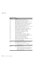
Страница 313: ...constant but the length of the pause between the beeps varies For example a 1 2 4 beep code sounds like one beep a pause two consecutive beeps another pause and four more consecutive beeps It is possi...

Страница 314: ...test is in progress or has failed Screen retrace tests are in progress or have failed Search for video ROM is in progress Screen believed operable Timer tick interrupt test is in progress or has fail...

Страница 315: ...on indicates a system memory error This combination occurs only if the video BIOS cannot display the error code Continuous Beep This beep type indicates that your server s system board or speaker subs...

Страница 316: ...onitor connection to the server Ensure that the monitor is connected to the server If the problem recurs have the system serviced Two Long and Two Short Beeps This beep combination indicates that POST...

Страница 317: ...suffer any damage CAUTION Observe all safety and electrostatic precautions listed in this book to avoid personal injury or damage to your system If the system does not work correctly turn it off and...

Страница 318: ...plug it in and turn on the server If it does not work correctly have the keyboard serviced If liquid gets inside the monitor 1 Turn off the monitor 2 Turn off the server 3 Unplug the monitor from the...

Страница 319: ...ion of the test to be run Command line parameters to be passed to the program identified in the first item on this list The PC Server Diagnostic Diskette includes a sample file called SAMPLE CFG The u...

Страница 320: ...ou have designated to contain the QA files that directory must be listed in the PATH section of the AUTOEXEC BAT 4 You can use a CFG file other than USERDIAG CFG if you use the command line USRCONFIG...

Страница 321: ...ine Modem Generic 1 Generic 2 CMD 1 CMD 2 CMD 3 The diagnostic program automatically assigns a test number to each test The test numbers start at 201 and continue upward as needed The numbers follow 2...

Страница 322: ...e editor allows you to modify text files By modifying files such as your AUTOEXEC BAT or CONFIG SYS files you can improve the test system s performance and eliminate unnecessary lines of information i...

Страница 323: ...g started with F4 press F5 If you did not previously press F4 to start marking a block of text F5 is ignored F6 To move an active marked block of text first press F6 while the cursor is within the act...

Страница 324: ...hey do not consider the requirements of the operating system or the application programs For these reasons memory address configuration conflicts might occur Resolving Memory Address Conflicts The Con...

Страница 325: ...to video read only memory ROM You can use the Configuration Setup utility program to view or change the current setting for video ROM If the SVGA or EMM386 device driver is causing the memory address...

Страница 326: ...Resolving Configuration Conflicts 312 PC Server 330 User s Handbook...

Страница 327: ...n that contains troubleshooting procedures and explanations of error messages For troubleshooting and error information about your PC Server 330 see Chapter 5 Solving Problems on page 227 If you suspe...

Страница 328: ...ions Multimedia The IBM PC Company Bulletin Board System BBS can be reached 24 hours a day 7 days a week Modem speeds of up to 14400 baud are supported Long distance telephone charges might apply To a...

Страница 329: ...ng system compatibility tests The following is a sample of the information available at http www pc ibm com servers on the World Wide Web A listing of products that have been tested for compatibility...

Страница 330: ...erver and IBM monitor Installing and setting up IBM options purchased from IBM or an IBM reseller 60 day preinstalled operating system support Arranging for service on site or carry in Arranging for o...

Страница 331: ...International Warranty Service in the U S or Canada call 1 800 497 7426 Purchasing Additional HelpWare Services During and after the warranty period you can purchase additional HelpWare services such...

Страница 332: ...nnual contract with a 10 incident limit For more information about purchasing Network and Server Support see Ordering Support Line Services Ordering Support Line Services Enhanced PC Support Line and...

Страница 333: ...gh Friday The premium upgrade provides 4 hour average response 24 hours a day 7 days a week On site service to premium on site service If your warranty provides for on site service you can upgrade to...

Страница 334: ...ations are available for purchase from IBM For a list of publications available in your country In the U S Canada and Puerto Rico call 1 800 879 2755 In other countries contact your IBM reseller or IB...

Страница 335: ...on For example the settings of jumpers J1 and J20 together define the clock speed of the microprocessor Two Pin Jumper Blocks Covering both pins with a jumper defines one function of the jumper block...

Страница 336: ...ith the two pins on the pin block and then slide the jumper onto these pins Align one of the holes in the bottom of the jumper with one of the pins on the pin block and then slide the jumper onto that...

Страница 337: ...er s position for a three pin jumper block 1 Turn off the server then disconnect the server power cord 2 Remove the server cover 3 Lift the jumper straight off the pin block 4 Align the holes in the b...

Страница 338: ...ystem board jumper block locations Ethernet Enable Jumper J22 SCSI Controller Enable Jumper J26 External SCSI Termination Jumper J38 Video Enable Jumper J25 Power On Password Jumper J12 System Managem...

Страница 339: ...osition if you are not using the SCSI controller on the system board for example if you install a SCSI adapter and plan to connect all drives to it By disabling the system board SCSI controller you fr...

Страница 340: ...power on password See Using the Power on Password Menu on page 100 Change the position of the power on password jumper When you restart the server POST proceeds without prompting for the password for...

Страница 341: ...nter pin and the pin that was not covered previously c Slide the jumper over these pins POST will bypass the power on password the next time that you restart the server 3 Replace the server cover and...

Страница 342: ...board jumper block locations Table 7 on page 329 contains the identifiers and description of the jumper blocks located on the processor board PMC Frequency Selection Jumper Clock Ratio Jumper Clock F...

Страница 343: ...performance Attention If the microprocessor bus to core ratio is incorrect system board components will overheat and component damage can occur Be sure that the microprocessor bus to core ratio jumper...

Страница 344: ...ssor that you installed Table 7 Page 2 of 2 Defining Microprocessor Operating Parameters Identifier Default Jumper Position Description J9 J10 J12 Reserved Table 8 Frequency Parameters Speed in MHz Mu...

Страница 345: ...cation numbers are located on a label on the rear of the server The server serial number is also located near the bottom on the front bezel Note Two keys are provided with your server Store the keys i...

Страница 346: ...system s default configuration settings This information can be helpful when you install additional options in your server or if you ever need to have your server serviced Copy these tables before re...

Страница 347: ...ation properly Table 9 Internal and External Drives and Devices Location Drive or Device Description Internal Devices Bay 1 Bay 2 Bay 3 Bay 4 Bay 5 Bay 6 5 25 Inch CD ROM Drive Bay 7 3 5 Inch 1 44 MB...

Страница 348: ...e cache size and type and the same clock speed as the primary microprocessor System Information Product Data Flash EEPROM Revision Level BIOS Date PCI Routing Planar SCSI IRQ IRQ15 Planar Ethernet IRQ...

Страница 349: ...d Cache Type Write Back Cache Size Video BIOS Caching Enabled Video Buffer Caching Disabled Option ROM Caching Disabled ROM Shadowing F0000h FFFFFh System BIOS Enabled E0000h EFFFFh System BIOS Enable...

Страница 350: ...MB Kit 128 MB Connector J5 32 MB Kit 64 MB Kit 128 MB Total Memory Record expansion slot configuration information for your server in the following table Table 12 Expansion Slot Configuration Informa...

Страница 351: ...J26 SCSI Bus Termination Jumper J38 External SCSI Connector J29 PCI Slots Video Enable J25 Video Connector Video RAM Sockets Processor Board Connector Power On Password Jumper J12 System Management E...

Страница 352: ...dule Connector Reserved Memory Connectors Secondary Microprocessor Connector Primary Microprocessor Fan Connector J22 Secondary Microprocessor Fan Connector J21 Primary Voltage Regulator Module Connec...

Страница 353: ...ed in a 10BASE T link segment do not require grounding However all of the devices connected to the cables must be grounded If your server comes with an Ethernet interface cable you must install it to...

Страница 354: ...link segments The following figure illustrates the RJ 45 connector 10BASE T UTP Cable RJ 45 Modular Plug Connector 1 2 3 Pins 6 Table 13 Cabling Specifications for 10BASE T Link Segments Characterist...

Страница 355: ...tes the wiring in crossover cables Twisted Pair 1 2 3 6 4 5 7 8 RJ 45 Modular Connector Pin 1 1 2 2 3 4 10BASE T Cable 1 2 3 6 4 5 7 8 Pin TD TD RD RD RJ 45 Modular Connector Not used TD TD RD RD Not...

Страница 356: ...port Table 14 Pin Assignments for AUI Port Pin Number Description 3 Data out 10 Data out 11 Digital ground 5 Data in 12 Data in 4 Digital ground 7 no connection 15 no connection 8 Digital ground 2 Co...

Страница 357: ...evaluation and verification of operation in conjunction with other products except those expressly designated by IBM are the responsibility of the user IBM may have patents or pending patent applicati...

Страница 358: ...ks or service marks of others Adaptec Adaptec Inc America Online America Online Inc ARCnet Datapoint Corporation CompuServe CompuServe Incorporated Intel Intel Corporation IPX Novel Inc LANtastic Arti...

Страница 359: ...t services 317 World Wide Web 16 315 adapter retention bracket 129 218 adapters changing jumpers 135 DASD status connectors 185 deactivated 113 adapters continued EISA slots 133 failure 65 installatio...

Страница 360: ...figuration 65 synchronize 29 with one hard disk drive 42 assistance and service 17 attaching internal drives 149 U bolt 215 attachment unit interface cable 341 connector location 10 automatic restart...

Страница 361: ...ecurity cover 217 specifications 339 straight through 339 cabling the server 221 cache See also the User s Reference control 102 Level 2 size 3 cache control 102 card See adapters caution clearances f...

Страница 362: ...architecture EISA Configuration Diskette 105 features and options 108 configuration continued extended industry standard architecture EISA continued view or edit details 107 files CFG 104 107 109 hard...

Страница 363: ...157 serial device 9 considerations microprocessor upgrade 202 software 20 controller See also the User s Reference video 311 controls 4 cord power See the User s Reference cover installing 220 lock 22...

Страница 364: ...rds 334 SCSI 157 static sensitive handling 125 device error table 63 DHS defunct hot spare 34 diagnostic description 230 diskette 288 formatting diskettes 308 insufficient memory for 238 main menu 234...

Страница 365: ...e for 151 installing all bays 162 CD ROM drives 200 diskette drives 165 in bays 1 2 164 in bays 3 8 non disk array models 175 drive continued interface 187 internal 149 150 155 introduction 149 locati...

Страница 366: ...T 231 246 247 SCO UNIX driver 278 SCSI 257 ServeRAID adapter 282 error messages continued software 233 software generated 231 SunSoft Solaris driver 278 types 231 246 UnixWare driver 278 Ethernet cont...

Страница 367: ...enable jumper J30 enable position 325 location 324 flickering monitor 290 forgotten administrator password 98 format low level disk array system 74 non disk array system 118 formatting drives 118 FRE...

Страница 368: ...ervice center See telephone numbers IBM identification numbers 331 in use lights 291 for CD ROM drive 6 for diskette drive 289 Standby mode 6 indicators 4 industry standard architecture ISA See ISA in...

Страница 369: ...ions 150 151 155 purpose 149 removing 170 190 SCSI 157 sizes 150 151 155 options installed 334 preinstalled 11 SCSI devices terminating 223 internal continued setting jumpers 163 international warrant...

Страница 370: ...8 Ethernet receive 7 Ethernet transmit 8 microprocessor activity 7 lights continued POST activity 8 power on 8 security 8 lights not working 291 liquid spilled on server 304 locations adapter 134 cov...

Страница 371: ...default settings 336 device records 334 problems 293 memory modules dual inline DIMMs 142 memory module kits device records 336 installing 143 purpose 142 removing 143 146 size 142 speed 142 system 14...

Страница 372: ...rea network and server startup support 316 and server support services fee 317 network continued Ethernet driver 258 operating systems compatibility 16 315 network adapter starting from 101 non disk a...

Страница 373: ...s 331 support line services 318 overview installing software 20 test programs 233 P Packet Driver messages 275 parallel port configuration 334 configuring 94 description 9 location 9 problems 294 test...

Страница 374: ...ower on password reset jumper J12 325 power on self test POST See also the User s Reference beep codes 230 299 during configuration 89 enhanced 101 message table 247 overview 229 quick 101 precautions...

Страница 375: ...r disk array 192 198 RAID redundant array of independent disks continued resetting the default values 75 technology 19 RAM random access memory See the User s Reference RBL rebuild 34 RDY ready 35 rea...

Страница 376: ...safety requirements electrical viii 124 general information 123 handling static sensitive devices 125 saving configuration settings 119 SBY standby 35 scanners SCSI 157 SCO OpenServer 5 0 21 SCO UNIX...

Страница 377: ...ages 149 cabling 221 door installing 182 193 removing 176 190 server continued identification numbers 331 illustrated views front 11 rear 9 installing cover 220 problems 233 records 333 334 336 securi...

Страница 378: ...133 expansion 133 135 ISA bus 133 PCI bus 133 position adapter 135 removing cover 136 slot continued screw 136 software error 233 296 problems 296 software installing 20 solving problems configuration...

Страница 379: ...fiers 325 jumper locations 324 problem 254 255 testing 238 system damage 303 system information 93 system management jumper J49 324 325 System Security menu administrator password 98 power on password...

Страница 380: ...51 155 U U bolt installing 215 installing 216 location 216 unattended mode ServeRAID 70 Unattended start mode enabling 96 setting 97 unblocking a logical drive 56 understanding hard disk drive capacit...

Страница 381: ...ation 29 virus checking 239 vital product data VPD See the User s Reference voltage regulator module VRM 202 209 W Wake Up on Ring 97 Wake Up Timer 97 warranty information See also the User s Referenc...

Страница 382: ...IBM Part Number 76H8834 Printed in U S A September 1996 76H8834...

Отзывы: