

4. The DIMM error LEDs, microprocessor error LEDs, and VRM error LEDs turn
off when the system is turned off.
Note:
See “System” on page 116 to determine which components should be replaced by a field service technician.
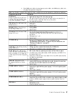
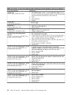
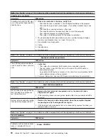
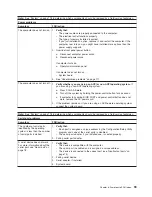
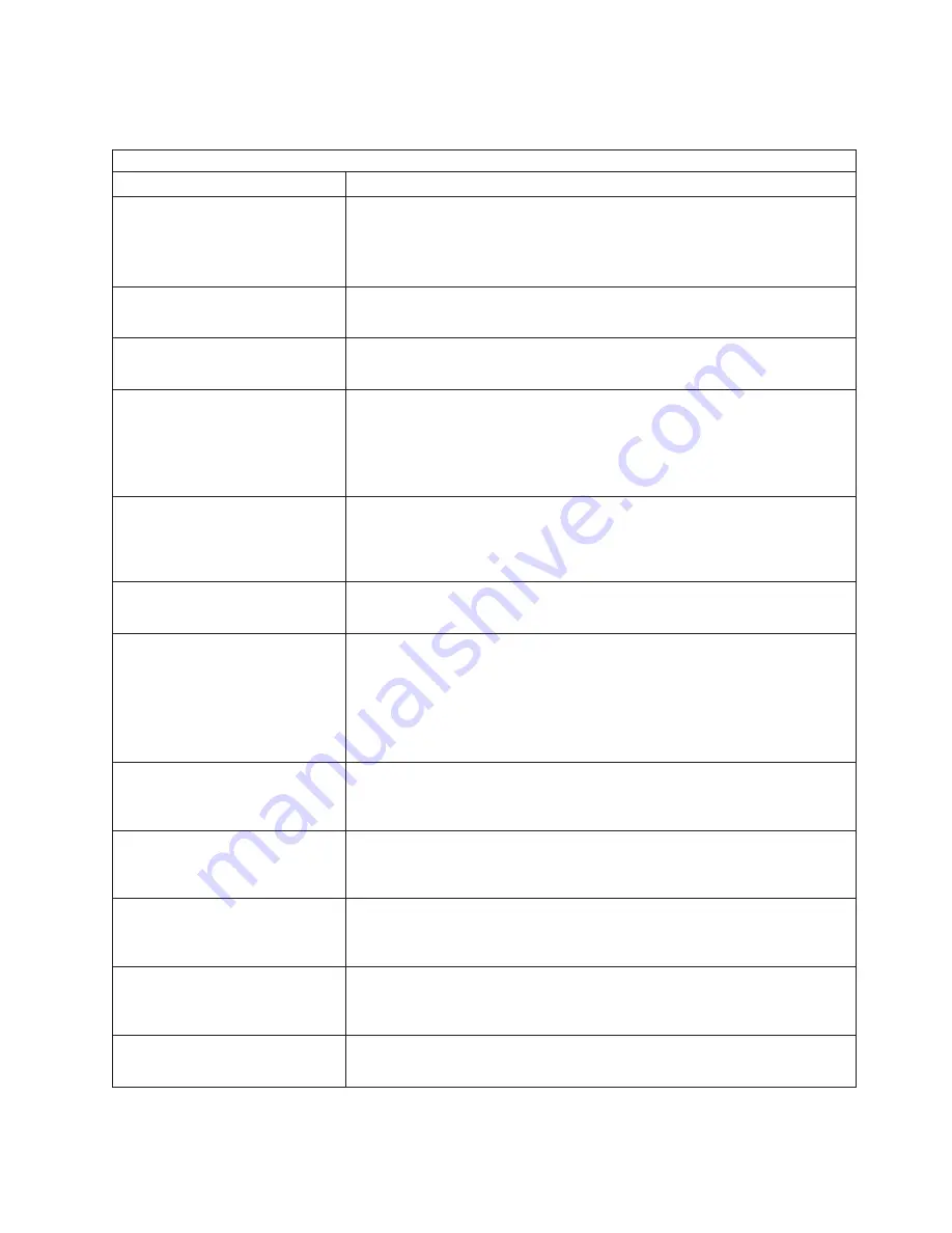
Diagnostics panel LED
FRU/action
All LEDs off
(Check System Error Log for error
condition, then clear System Error
Log when the problem is found.)
1.
System Error Log is 75% full; clear the log.
2. PFA alert; check log for failure; clear PFA alert; remove ac power for at
least 20 seconds, reconnect, then turn on the system.
3. Run light path diagnostics.
FAN LED on
(The LED next to the
failing fan is on.)
1.
Failing fan.
2. System board
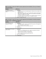
MEMORY LED on
(The LED next
to the failing DIMM is on.)
1.
Failing DIMM.
2. System board
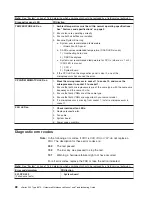
CPU LED on
(The LED next to the
failing CPU is on.)
1.
Run the Configuration/Setup Utility program
to verify that all
microprocessors have identical cache sizes, dock speeds and clock
frequencies.
2. Microprocessor 1 or 2.
3. System board.
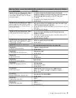
PCI BUS LED on
1.
Remove all PCI adapters from slots on affected bus (see
“System-board LED locations” on page 49 for bus information, see
“Working with adapters” on page 51).
2. System board.
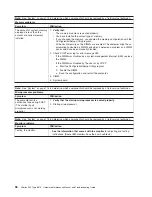
VRM LED on
(The LED next to the
failing VRM is on.)
1.
Voltage regulator module indicated by the lit VRM LED.
2. Microprocessor indicated by the microprocessor LED.
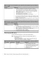
DASD LED on
(The LED located
next to the drive bay that the failing
drive is installed in is lit. Check the
amber drive LED for the failing hard
drive.)
1.
Be sure the fans are operating correctly and the airflow is good.
2. If installed, reseat I2C cable between DASD backplane and DASD I2C on
the system board (J10).
3. Failing drive. SCSI channel A has failed. (This is the SCSI channel for the
hot-swap hard disk drives).
4. DASD backplane.
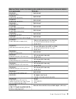
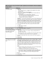
ISMP LED
(Integrated System
Management detects an internal
error.)
1. .
Update ISMP firmware with latest level code. Unplug AC power from
the server for at least 30 seconds, and then retry.
2. System board.
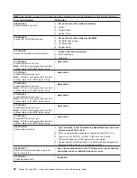
POWER SUPPLY 1 LED on
1.
Check the dc good LED on power supply 1. If it is off, replace power
supply 1.
2. Power cage assembly.
POWER SUPPLY 2 LED on
1.
Check the dc good LED on power supply 2. If it is off, replace power
supply 2.
2. Power cage assembly.
NONREDUNDANT LED on
1.
Check the PS1 and PS2 LEDs and replace any indicated power supply.
2. Install an additional power supply or remove optional devices from the
server.
NMI LED on
1.
Restart the server.
2. Check the System Error Log.
Chapter 6. Symptom-to-FRU index
87
Содержание eServer xSeries 345 Type 8670
Страница 1: ...xSeries 345 Type 8670 Hardware Maintenance Manual and Troubleshooting Guide ERserver...
Страница 2: ......
Страница 3: ...xSeries 345 Type 8670 Hardware Maintenance Manual and Troubleshooting Guide ERserver...
Страница 6: ...iv xSeries 345 Type 8670 Hardware Maintenance Manual and Troubleshooting Guide...
Страница 10: ...viii xSeries 345 Type 8670 Hardware Maintenance Manual and Troubleshooting Guide...
Страница 18: ...8 xSeries 345 Type 8670 Hardware Maintenance Manual and Troubleshooting Guide...
Страница 88: ...78 xSeries 345 Type 8670 Hardware Maintenance Manual and Troubleshooting Guide...
Страница 124: ...114 xSeries 345 Type 8670 Hardware Maintenance Manual and Troubleshooting Guide...
Страница 130: ...120 xSeries 345 Type 8670 Hardware Maintenance Manual and Troubleshooting Guide...
Страница 141: ...Chapter 8 Related service information 131...
Страница 142: ...132 xSeries 345 Type 8670 Hardware Maintenance Manual and Troubleshooting Guide...
Страница 143: ...Chapter 8 Related service information 133...
Страница 144: ...134 xSeries 345 Type 8670 Hardware Maintenance Manual and Troubleshooting Guide...
Страница 145: ...Chapter 8 Related service information 135...
Страница 146: ...136 xSeries 345 Type 8670 Hardware Maintenance Manual and Troubleshooting Guide...
Страница 147: ...Chapter 8 Related service information 137...
Страница 157: ...Chapter 8 Related service information 147...
Страница 158: ...148 xSeries 345 Type 8670 Hardware Maintenance Manual and Troubleshooting Guide...
Страница 159: ...Chapter 8 Related service information 149...
Страница 160: ...150 xSeries 345 Type 8670 Hardware Maintenance Manual and Troubleshooting Guide...
Страница 161: ...Chapter 8 Related service information 151...
Страница 162: ...152 xSeries 345 Type 8670 Hardware Maintenance Manual and Troubleshooting Guide...
Страница 166: ...156 xSeries 345 Type 8670 Hardware Maintenance Manual and Troubleshooting Guide...
Страница 174: ...164 xSeries 345 Type 8670 Hardware Maintenance Manual and Troubleshooting Guide...
Страница 175: ......
Страница 176: ...Part Number 48P9718 1P P N 48P9718...