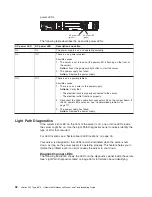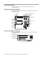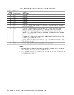
2. The server supports a maximum of three PCI buses.
3. See the documentation that comes with the system-management software for
more information about the service processor.
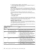
Remind button
You can use the Remind button to place the front panel system-error LED into the
Remind mode. By pressing the button, you acknowledge the failure but indicate that
you will not take immediate action. If a new failure occurs, the system-error LED will
turn on again.
In the Remind mode, the system-error LED flashes every 2 seconds. The
system-error LED remains in the Remind mode until one of the following situations
occurs:
v
All known problems are resolved
v
The system is restarted
v
A new problem occurs
You can use the Remind button to delay server maintenance until a later time. Also,
resetting the system-error LED enables the LED to react to another error. If the LED
is still flashing from the first error, it will not mask additional errors.
Light Path Diagnostics table
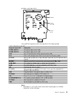
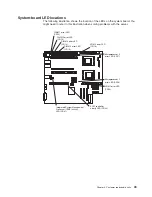
The System error LED on the front of the server is lit when certain system errors
occur. If the System error LED on your server is lit, check to see which of the LEDs
on the diagnostics panel inside the server are on.
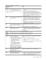
Use the following table to help determine the cause of the error and the action you
should take when the system error LED is on and:
Table 5. Light Path Diagnostics
Diagnostics
panel LED
on
Cause
Action
None
The system error log is 75% or more
full or a PFA alert was logged.
Check the system error log and correct any problems.
Disconnecting the server from all power sources for at least 20
seconds will turn off the system error LED.
CPU
One of the microprocessors has
failed, or a microprocessor is
installed in the wrong socket.
1. Check the microprocessor error LEDs on the system
board. If a microprocessor error LED is on for a
microprocessor socket that is empty, the microprocessors
are not installed in the correct order (see “Installing an
additional microprocessor” on page 60).
2. Turn off the server, reseat the microprocessor indicated by
the lit microprocessor error LED, and restart the server.
3. If the problem remains, replace the microprocessor.
VRM
One of the microprocessor VRMs has
failed.
1. Check the microprocessor VRM connectors on the system
board to locate the error LED next to the failing
component. See “Installing an additional microprocessor”
on page 60 for information about installing VRMs.
2. Turn off the server, reseat the microprocessor VRM
indicated by the lit VRM error LED, and restart the server.
3. If the problem remains, replace the microprocessor VRM.
MEMORY
A memory error occurred.
1. Check the DIMM error LEDs on the system board.
2. Replace the DIMM indicated by the lit DIMM error LED.
34
xSeries 345 Type 8670: Hardware Maintenance Manual and Troubleshooting Guide
Содержание eServer xSeries 345 Type 8670
Страница 1: ...xSeries 345 Type 8670 Hardware Maintenance Manual and Troubleshooting Guide ERserver...
Страница 2: ......
Страница 3: ...xSeries 345 Type 8670 Hardware Maintenance Manual and Troubleshooting Guide ERserver...
Страница 6: ...iv xSeries 345 Type 8670 Hardware Maintenance Manual and Troubleshooting Guide...
Страница 10: ...viii xSeries 345 Type 8670 Hardware Maintenance Manual and Troubleshooting Guide...
Страница 18: ...8 xSeries 345 Type 8670 Hardware Maintenance Manual and Troubleshooting Guide...
Страница 88: ...78 xSeries 345 Type 8670 Hardware Maintenance Manual and Troubleshooting Guide...
Страница 124: ...114 xSeries 345 Type 8670 Hardware Maintenance Manual and Troubleshooting Guide...
Страница 130: ...120 xSeries 345 Type 8670 Hardware Maintenance Manual and Troubleshooting Guide...
Страница 141: ...Chapter 8 Related service information 131...
Страница 142: ...132 xSeries 345 Type 8670 Hardware Maintenance Manual and Troubleshooting Guide...
Страница 143: ...Chapter 8 Related service information 133...
Страница 144: ...134 xSeries 345 Type 8670 Hardware Maintenance Manual and Troubleshooting Guide...
Страница 145: ...Chapter 8 Related service information 135...
Страница 146: ...136 xSeries 345 Type 8670 Hardware Maintenance Manual and Troubleshooting Guide...
Страница 147: ...Chapter 8 Related service information 137...
Страница 157: ...Chapter 8 Related service information 147...
Страница 158: ...148 xSeries 345 Type 8670 Hardware Maintenance Manual and Troubleshooting Guide...
Страница 159: ...Chapter 8 Related service information 149...
Страница 160: ...150 xSeries 345 Type 8670 Hardware Maintenance Manual and Troubleshooting Guide...
Страница 161: ...Chapter 8 Related service information 151...
Страница 162: ...152 xSeries 345 Type 8670 Hardware Maintenance Manual and Troubleshooting Guide...
Страница 166: ...156 xSeries 345 Type 8670 Hardware Maintenance Manual and Troubleshooting Guide...
Страница 174: ...164 xSeries 345 Type 8670 Hardware Maintenance Manual and Troubleshooting Guide...
Страница 175: ......
Страница 176: ...Part Number 48P9718 1P P N 48P9718...

