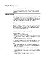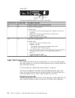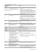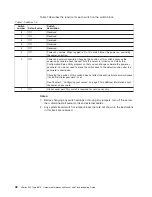
Table 5. Light Path Diagnostics (continued)
Diagnostics
panel LED
on
Cause
Action
PCI BUS A
PCI BUS B
PCI BUS C
An error occurred on PCI bus A, B,
or C. An adapter in PCI slot 1, 2, 3,
4, or 5 or the system board caused
the error.
1. Check the adapter slots to locate the error LED next to the
failing bus.
2. Check the error log for additional information.
3. If you cannot correct the problem from the error LED or
information in the error log, try to determine the failing
adapter by removing one adapter at a time from PCI bus A
(PCI-X slots 1 or 2), PCI bus B (PCI-X slots 3 or 4), or PCI
bus C (PCI slot 5) and restarting the server after each
adapter is removed.
DASD
A hot-swap hard disk drive has failed
on SCSI channel B.
1. Check the error log for additional information. If the error
log indicates a temperature problem and the fans are
working correctly, verify that the ambient temperature is
within normal limits (see “Features and specifications” on
page 3).
2. If the amber hard disk status LED on one of the hot-swap
hard disk drives is on, see “Server controls and indicators”
on page 4 for more information.
NMI
A nonmaskable interrupt occurred.
The PCI BUS LED will probably also
be on.
If the PCI BUS LED is on, follow the instructions for those
LEDs.
If the PCI BUS LED is not on, restart the server.
ISMP
Integrated System management
detects an internal error.
1. Update ISMP firmware with latest level code. Unplug ac
power, wait at least 30 seconds before restarting the
system.
2. System board
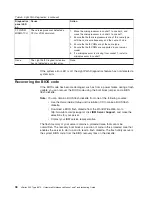
POWER
SUPPLY 1
The power supply in bay 1 has failed. Replace the power supply in bay 1.
POWER
SUPPLY 2
The power supply in bay 2 has failed. Replace the power supply in bay 2.
NON-RED
The server is operating in a
nonredundant power mode, if:
v
Two power supplies are installed in
the server, and one power supply
has either failed or is not
connected to a functioning ac
electrical outlet.
v
The system has exceeded the
power capabilities of one of the
redundant power supplies.
Note:
This LED will not be lit if your
server has only one power supply;
however, the power is not redundant
with only one power supply installed.
Check the power supply LEDs to determine the failing power
supply.
1. Check the power supply connections.
2. If a power supply has failed, replace the failing power
supply.
3. If neither LED is lit, you can remove optional devices from
the server to restore redundancy.
FAN
One of the fans has failed or is
operating too slowly.
Note:
A failing fan can also cause
the TEMP and DASD LEDs to be on.
The LED on the failing fan will be lit. Replace the fan.
TEMP
The system temperature has
exceeded the maximum rating.
1. Check to see if a fan has failed. If it has, replace the fan.
2. Make sure the room temperature is not too high. (See
“Features and specifications” on page 3.)
Chapter 3. Diagnostics
35
Содержание eServer xSeries 345 Type 8670
Страница 1: ...xSeries 345 Type 8670 Hardware Maintenance Manual and Troubleshooting Guide ERserver...
Страница 2: ......
Страница 3: ...xSeries 345 Type 8670 Hardware Maintenance Manual and Troubleshooting Guide ERserver...
Страница 6: ...iv xSeries 345 Type 8670 Hardware Maintenance Manual and Troubleshooting Guide...
Страница 10: ...viii xSeries 345 Type 8670 Hardware Maintenance Manual and Troubleshooting Guide...
Страница 18: ...8 xSeries 345 Type 8670 Hardware Maintenance Manual and Troubleshooting Guide...
Страница 88: ...78 xSeries 345 Type 8670 Hardware Maintenance Manual and Troubleshooting Guide...
Страница 124: ...114 xSeries 345 Type 8670 Hardware Maintenance Manual and Troubleshooting Guide...
Страница 130: ...120 xSeries 345 Type 8670 Hardware Maintenance Manual and Troubleshooting Guide...
Страница 141: ...Chapter 8 Related service information 131...
Страница 142: ...132 xSeries 345 Type 8670 Hardware Maintenance Manual and Troubleshooting Guide...
Страница 143: ...Chapter 8 Related service information 133...
Страница 144: ...134 xSeries 345 Type 8670 Hardware Maintenance Manual and Troubleshooting Guide...
Страница 145: ...Chapter 8 Related service information 135...
Страница 146: ...136 xSeries 345 Type 8670 Hardware Maintenance Manual and Troubleshooting Guide...
Страница 147: ...Chapter 8 Related service information 137...
Страница 157: ...Chapter 8 Related service information 147...
Страница 158: ...148 xSeries 345 Type 8670 Hardware Maintenance Manual and Troubleshooting Guide...
Страница 159: ...Chapter 8 Related service information 149...
Страница 160: ...150 xSeries 345 Type 8670 Hardware Maintenance Manual and Troubleshooting Guide...
Страница 161: ...Chapter 8 Related service information 151...
Страница 162: ...152 xSeries 345 Type 8670 Hardware Maintenance Manual and Troubleshooting Guide...
Страница 166: ...156 xSeries 345 Type 8670 Hardware Maintenance Manual and Troubleshooting Guide...
Страница 174: ...164 xSeries 345 Type 8670 Hardware Maintenance Manual and Troubleshooting Guide...
Страница 175: ......
Страница 176: ...Part Number 48P9718 1P P N 48P9718...

