Attention:
Expansion-slot covers must be installed on all empty slots. This
maintains the electronic emissions characteristics of the system and ensures
proper cooling of system components.
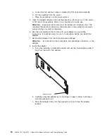
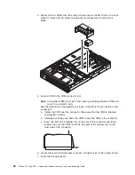
4. Install the low profile 2-U bracket on the adapter:
a. Remove the adapter from the static-protective package. Set the adapter
down on a nonconductive, static-protected surface (place it component side
up).
Attention:
Avoid touching the components and gold-edge connectors on
the adapter.
b. Remove the 3-U bracket from the adapter and replace it with the 2-U low
profile bracket that comes with the RAID controller option. See the
documentation that comes with your RAID controller option for instructions.
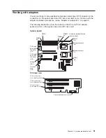
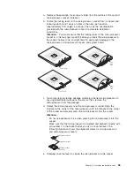
5. Install the adapter:
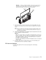
a. Carefully grasp the adapter by its top edge or upper corners, and align it
with the expansion slot on the system board.
b. Press the adapter
firmly
into the expansion slot and close the adapter
retainer.
Attention:
When you install an adapter in the server, be sure that it is
completely and correctly seated in the connector. Incomplete insertion might
cause damage to the system board or the adapter.
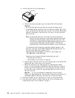
6. If you have other options to install or remove, do so now; otherwise, go to
“Installing the server cover and bezel” on page 71.
Installing a hot-swap drive
Your server supports six 1-inch (26 mm) slim 3.5-inch low voltage differential (LVD)
hard disk drives.
Each hot-swap drive has two indicator LEDs. If the amber hard disk drive status
LED is lit continuously, that drive is faulty and requires replacement. When the hard
disk status LED indicates a drive fault, you can replace a hot-swap drive without
turning off the server.
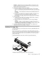
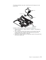
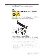
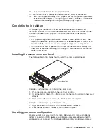
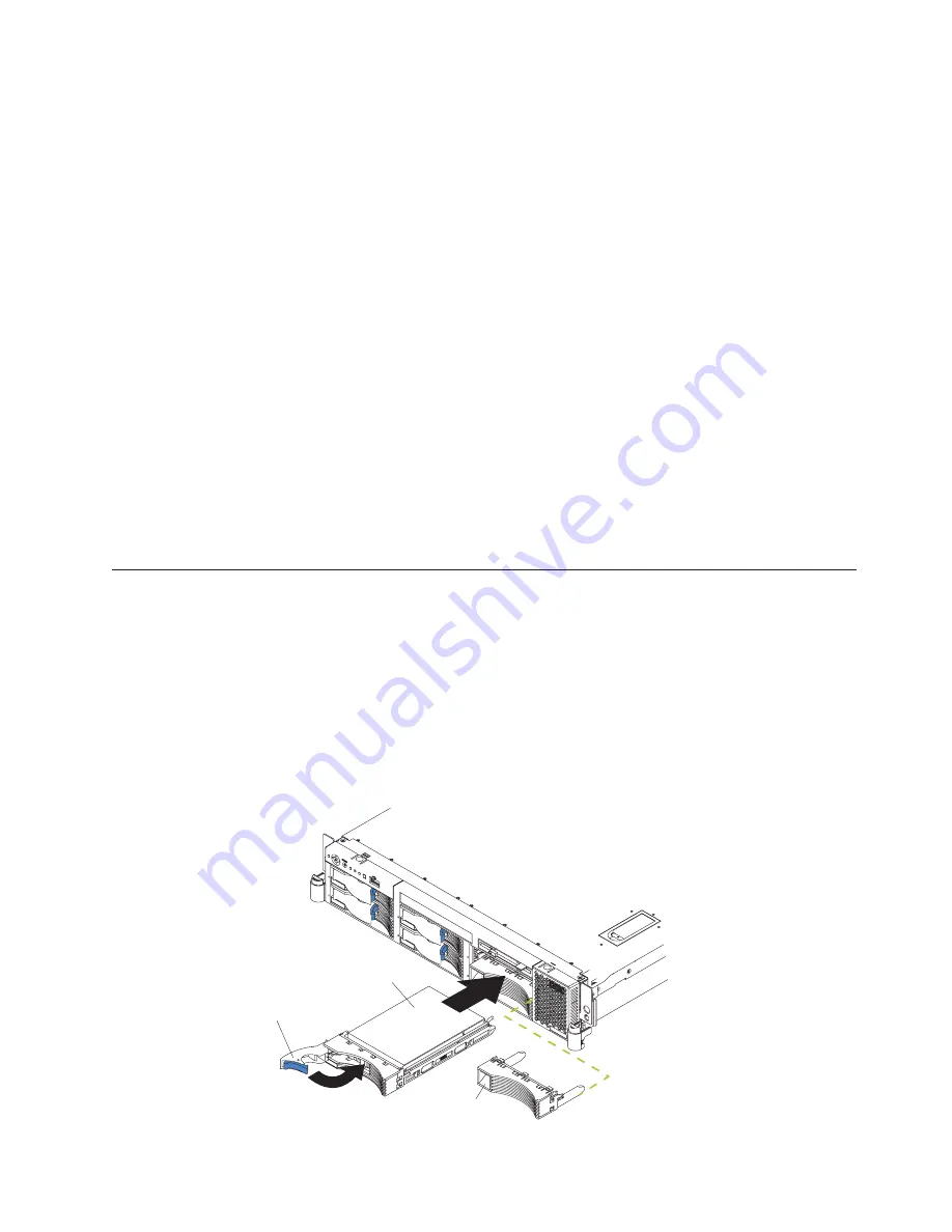
The following illustration shows how to install a hot-swap hard disk drive.
Filler panel
Drive-tray assembly
Drive handle
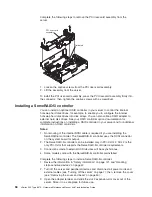
Complete the following steps to install a drive in a hot-swap bay.
Chapter 4. Customer replaceable units
57
Содержание eServer xSeries 345 Type 8670
Страница 1: ...xSeries 345 Type 8670 Hardware Maintenance Manual and Troubleshooting Guide ERserver...
Страница 2: ......
Страница 3: ...xSeries 345 Type 8670 Hardware Maintenance Manual and Troubleshooting Guide ERserver...
Страница 6: ...iv xSeries 345 Type 8670 Hardware Maintenance Manual and Troubleshooting Guide...
Страница 10: ...viii xSeries 345 Type 8670 Hardware Maintenance Manual and Troubleshooting Guide...
Страница 18: ...8 xSeries 345 Type 8670 Hardware Maintenance Manual and Troubleshooting Guide...
Страница 88: ...78 xSeries 345 Type 8670 Hardware Maintenance Manual and Troubleshooting Guide...
Страница 124: ...114 xSeries 345 Type 8670 Hardware Maintenance Manual and Troubleshooting Guide...
Страница 130: ...120 xSeries 345 Type 8670 Hardware Maintenance Manual and Troubleshooting Guide...
Страница 141: ...Chapter 8 Related service information 131...
Страница 142: ...132 xSeries 345 Type 8670 Hardware Maintenance Manual and Troubleshooting Guide...
Страница 143: ...Chapter 8 Related service information 133...
Страница 144: ...134 xSeries 345 Type 8670 Hardware Maintenance Manual and Troubleshooting Guide...
Страница 145: ...Chapter 8 Related service information 135...
Страница 146: ...136 xSeries 345 Type 8670 Hardware Maintenance Manual and Troubleshooting Guide...
Страница 147: ...Chapter 8 Related service information 137...
Страница 157: ...Chapter 8 Related service information 147...
Страница 158: ...148 xSeries 345 Type 8670 Hardware Maintenance Manual and Troubleshooting Guide...
Страница 159: ...Chapter 8 Related service information 149...
Страница 160: ...150 xSeries 345 Type 8670 Hardware Maintenance Manual and Troubleshooting Guide...
Страница 161: ...Chapter 8 Related service information 151...
Страница 162: ...152 xSeries 345 Type 8670 Hardware Maintenance Manual and Troubleshooting Guide...
Страница 166: ...156 xSeries 345 Type 8670 Hardware Maintenance Manual and Troubleshooting Guide...
Страница 174: ...164 xSeries 345 Type 8670 Hardware Maintenance Manual and Troubleshooting Guide...
Страница 175: ......
Страница 176: ...Part Number 48P9718 1P P N 48P9718...

