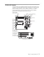

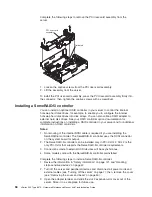
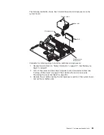
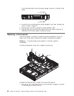

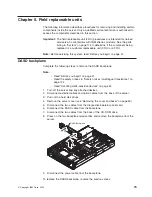
a. Remove the protective cover, tape or label from the surface of the second
microprocessor socket, if present.
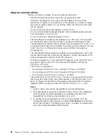
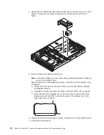
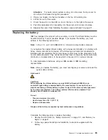
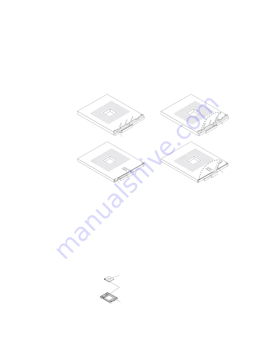
b. Rotate the locking lever on the microprocessor socket from its closed and
locked position until it stops or clicks in the fully open position
(approximately 135° angle), as shown. Then, see the documentation
provided with the microprocessor option for complete installation
instructions.
Attention:
You must ensure that the locking lever on the microprocessor
socket is in the fully open position before you insert the microprocessor in
the socket. Failure to do so might result in permanent damage to the
microprocessor, microprocessor socket, and system board.
Lever closed
Lever
fully
open
Lever closed
Lever
fully
open
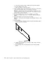
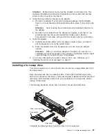
c. Touch the static-protective package containing the new microprocessor to
any
unpainted
metal surface on the server; then, remove the
microprocessor from the package.
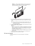
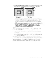
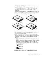
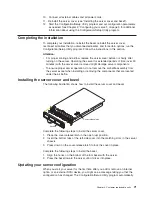
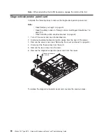
d. Center the microprocessor over the microprocessor socket. Align the
triangle on the corner of the microprocessor with the triangle on the corner
of the socket and carefully press the microprocessor into the socket.
Attention:
v
Do not use excessive force when pressing the microprocessor into the
socket.
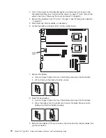
v
Make sure that the microprocessor is oriented and aligned correctly with
pin number 1 in the socket before you try to close the lever. The
following illustration shows the alignment marks for microprocessor 2
and microprocessor socket 2.
Microprocessor 2
Microprocessor
socket 2
Alignment marks
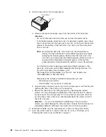
e. Carefully close the lever to secure the microprocessor in the socket.
Chapter 4. Customer replaceable units
65
Содержание eServer xSeries 345 Type 8670
Страница 1: ...xSeries 345 Type 8670 Hardware Maintenance Manual and Troubleshooting Guide ERserver...
Страница 2: ......
Страница 3: ...xSeries 345 Type 8670 Hardware Maintenance Manual and Troubleshooting Guide ERserver...
Страница 6: ...iv xSeries 345 Type 8670 Hardware Maintenance Manual and Troubleshooting Guide...
Страница 10: ...viii xSeries 345 Type 8670 Hardware Maintenance Manual and Troubleshooting Guide...
Страница 18: ...8 xSeries 345 Type 8670 Hardware Maintenance Manual and Troubleshooting Guide...
Страница 88: ...78 xSeries 345 Type 8670 Hardware Maintenance Manual and Troubleshooting Guide...
Страница 124: ...114 xSeries 345 Type 8670 Hardware Maintenance Manual and Troubleshooting Guide...
Страница 130: ...120 xSeries 345 Type 8670 Hardware Maintenance Manual and Troubleshooting Guide...
Страница 141: ...Chapter 8 Related service information 131...
Страница 142: ...132 xSeries 345 Type 8670 Hardware Maintenance Manual and Troubleshooting Guide...
Страница 143: ...Chapter 8 Related service information 133...
Страница 144: ...134 xSeries 345 Type 8670 Hardware Maintenance Manual and Troubleshooting Guide...
Страница 145: ...Chapter 8 Related service information 135...
Страница 146: ...136 xSeries 345 Type 8670 Hardware Maintenance Manual and Troubleshooting Guide...
Страница 147: ...Chapter 8 Related service information 137...
Страница 157: ...Chapter 8 Related service information 147...
Страница 158: ...148 xSeries 345 Type 8670 Hardware Maintenance Manual and Troubleshooting Guide...
Страница 159: ...Chapter 8 Related service information 149...
Страница 160: ...150 xSeries 345 Type 8670 Hardware Maintenance Manual and Troubleshooting Guide...
Страница 161: ...Chapter 8 Related service information 151...
Страница 162: ...152 xSeries 345 Type 8670 Hardware Maintenance Manual and Troubleshooting Guide...
Страница 166: ...156 xSeries 345 Type 8670 Hardware Maintenance Manual and Troubleshooting Guide...
Страница 174: ...164 xSeries 345 Type 8670 Hardware Maintenance Manual and Troubleshooting Guide...
Страница 175: ......
Страница 176: ...Part Number 48P9718 1P P N 48P9718...