background image

xSeries 345 Type 8670

Hardware Maintenance Manual and Troubleshooting
Guide

E

Rserver

򔻐򗗠򙳰

Содержание eServer xSeries 345 Type 8670

Страница 1: ...xSeries 345 Type 8670 Hardware Maintenance Manual and Troubleshooting Guide ERserver...

Страница 2: ......

Страница 3: ...xSeries 345 Type 8670 Hardware Maintenance Manual and Troubleshooting Guide ERserver...

Страница 4: ...uary 2003 The most recent version of this document is available on the World Wide Web at http www ibm com pc support Copyright International Business Machines Corporation 2002 All rights reserved US G...

Страница 5: ...e Sicherheitshinweise bevor Sie eine Anweisung ausf hren Accertarsi di leggere tutti gli avvisi di attenzione e di pericolo prima di effettuare qualsiasi operazione Lea atentamente todas las declaraci...

Страница 6: ...iv xSeries 345 Type 8670 Hardware Maintenance Manual and Troubleshooting Guide...

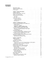
Страница 7: ...erveRAID Manager in Startable CD mode 13 Using the LSI Logic Configuration Utility program 20 Formatting a SCSI hard disk drive 21 Updating the integrated system management firmware 21 Configuring the...

Страница 8: ...emory modules 58 Installing an additional microprocessor 60 Installing a hot swap power supply 67 Replacing a hot swap fan 68 Replacing the battery 69 Completing the installation 71 Installing the ser...

Страница 9: ...evices 124 Grounding requirements 124 Safety notices multilingual translations 124 Appendix A Getting help and technical assistance 157 Before you call 157 Using the documentation 157 Getting help and...

Страница 10: ...viii xSeries 345 Type 8670 Hardware Maintenance Manual and Troubleshooting Guide...

Страница 11: ...is Hardware Maintenance Manual and Troubleshooting Guide is provided in PDF on the IBM xSeries Documentation CD It contains information to help you solve the problem yourself or to provide helpful inf...

Страница 12: ...k v Note These notices provide important tips guidance or advice v Important These notices provide information or advice that might help you avoid inconvenient or problem situations v Attention These...

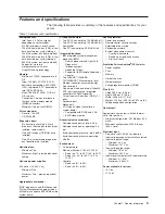
Страница 13: ...terconnect port Dedicated I O port Support for IBM Remote Supervisor Adapter v Two 10BASE T 100BASE TX 1000BASE T Ethernet ports Intel Ethernet controller on system board v One serial port v One exter...

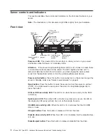
Страница 14: ...server you must unplug the server power cords from the electrical outlets or from the uninterruptible power device Power control button Press this button to manually turn on the server and put the ser...

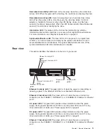
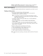
Страница 15: ...er maintenance is complete Rear view This section identifies the indicators on the rear of your server Ethernet 2 link status green LED Ethernet 1 link status green LED Ethernet 2 activity green LED E...

Страница 16: ...server v If the server is turned on and a power failure occurs it restarts automatically when power is restored v You can turn on the server by using the Integrated System Management Processor ISMP v...

Страница 17: ...you turn off the server wait at least 5 seconds before you turn on the server again b You might need to press and hold the power control button for more than 4 seconds to cause an immediate shutdown...

Страница 18: ...8 xSeries 345 Type 8670 Hardware Maintenance Manual and Troubleshooting Guide...

Страница 19: ...figure your disk array subsystem before you install your operating system See Using ServeRAID Manager on page 13 for more information v LSI Logic Configuration Utility With the built in LSI Logic Conf...

Страница 20: ...rver model and not all server models run utility programs from the System Partition To determine which ones do start the ServerGuide Setup and Installation CD and view the online overview After setup...

Страница 21: ...de If you have already configured the server hardware and you decide not to use the ServerGuide program to install your NOS complete the following steps to download the latest NOS installation instruc...

Страница 22: ...Setup Utility program and change the power on password Notes 1 Before changing any switch settings or moving any jumpers turn off the server then disconnect all power cords and external cables 2 Any s...

Страница 23: ...ssociated devices v Monitor operation of your RAID controllers The ServeRAID Manager program operates in two ways v Startable CD mode v As an installed software program The following sections provide...

Страница 24: ...Custom Express configuration automatically configures your controller and you can use Custom configuration to configure your controller manually Note If the integrated RAID controller has two channel...

Страница 25: ...remove the CD from the CD ROM drive Restart the server Using Customer configuration To configure your controller manually select Custom configuration Using Custom configuration you can select which tw...

Страница 26: ...e the following steps if you want to configure a hot spare drive a Click the Spares tab b Select the physical drive you want to designate as the hot spare drive then click Add selected drives 7 Click...

Страница 27: ...ager program and remove the CD from the CD ROM drive 11 Restart the server Viewing your configuration You can use ServeRAID Manager to view information about RAID controllers and the RAID subsystem su...

Страница 28: ...sistance For more information about ServeRAID Manager see the online help system To start the help system either click Information about this window on the toolbar or select an item from the Help menu...

Страница 29: ...rveRAID Manager tree objects and the actions that apply to them select a tree object and click Actions Hints and tips ServeRAID Assist will start and information about the tree object will appear in t...

Страница 30: ...RAID levels If a ServeRAID 5i controller is installed and later removed you must re enable the on board SCSI controller in using the Configuration Setup Utility program see Starting the Configuration...

Страница 31: ...Firmware Update Utility diskette that is used to update the ISM firmware This diskette updates the ISM firmware only and does not affect any device drivers Complete the following steps to update the...

Страница 32: ...and fault tolerance when running with Windows NT Windows 2000 or NetWare 4 1x or later v Adapter fault tolerance AFT provides automatic redundancy for the Ethernet controller If the primary controller...

Страница 33: ...1p or if you are not sure use High Priority Queue HPQ to prioritize network traffic The requirements for effectively using IEEE 802 1p tagging are v The other devices receiving and routing 802 1p tag...

Страница 34: ...s NT VLANS cannot be implemented on controllers that have been configured for teaming options Netware can support teaming options and VLANS on the same adapters Complete the following steps to join a...

Страница 35: ...ccur the next time you run the test A failed system might be part of a shared DASD cluster two or more systems sharing one or more external storage devices Before you run diagnostics verify that the f...

Страница 36: ...on page 101 7 Check the information LED panel System Error LED if it is on see Diagnostic panel system error LED on page 86 8 Check the System Error log If an error was recorded by the system see Cha...

Страница 37: ...he major components of your server See Diagnostic programs and error messages on page 29 for more information v Light Path Diagnostics Your server has light emitting diodes LEDs to help you identify p...

Страница 38: ...mn Table 3 ServerGuide Setup and Installation CD Symptom Suggested action The ServerGuide Setup and Installation CD will not start v Ensure that the server is supported and has a startable bootable CD...

Страница 39: ...is as follows fff ttt iii date cc text message where fff is the three digit function code that indicates the function being tested when the error occurred For example function code 089 is for the micr...

Страница 40: ...follow the instructions on the screen Notes a You can press F1 while running the diagnostic programs to obtain help information You also can press F1 from within a help screen to obtain online documen...

Страница 41: ...that might appear when you run the diagnostic programs see Diagnostic error codes on page 88 Notes 1 Depending on your server configuration some of the error messages might not appear when you run the...

Страница 42: ...J25 on the system board If the AC power LED comes on see Undetermined problems on page 111 3 The power supply has failed Action Replace the power supply Light Path Diagnostics If the system error LED...

Страница 43: ...es DIMMs failed OVER SPEC The system has shutdown due to a system over load condition DASD The SCSI backplane or a device connected to a SCSI bus failure NMI Nonmaskable interrupt occurred PCI BUS A E...

Страница 44: ...system error LED is on and Table 5 Light Path Diagnostics Diagnostics panel LED on Cause Action None The system error log is 75 or more full or a PFA alert was logged Check the system error log and c...

Страница 45: ...SMP Integrated System management detects an internal error 1 Update ISMP firmware with latest level code Unplug ac power wait at least 30 seconds before restarting the system 2 System board POWER SUPP...

Страница 46: ...g the BIOS code If the BIOS code has become damaged such as from a power failure during a flash update you can recover the BIOS code using the boot block jumper and a BIOS flash diskette Note You can...

Страница 47: ...onnect all power cords 6 Restart the server The system begins the power on self test POST 7 Select 1 Update POST BIOS from the menu that contains various flash update options 8 When prompted as to whe...

Страница 48: ...1000 Mbps Ethernet controller Network connection problems If the Ethernet controller cannot connect to the network check the following conditions v Make sure that the cable is installed correctly The...

Страница 49: ...for NetWare Versions 3 and 4 it is recommended that disk controllers not share interrupts with LAN controllers v Make sure that you are using the most recent device driver available from the World Wid...

Страница 50: ...ction well when they share an interrupt with a dissimilar PCI device Try changing the IRQ assigned to the Ethernet adapter or the other device v Reseat or replace the adapter The Ethernet controller s...

Страница 51: ...roperly grounded electrical outlets for your server monitor and any other options that you intend to install v Back up all important data before you make changes to disk drives v For a list of support...

Страница 52: ...ricity can damage electronic devices and your server To avoid damage keep static sensitive devices in their static protective packages until you are ready to install them To reduce the possibility of...

Страница 53: ...ard VRM Filler panel for drive bay Hot swap power supply Heat sink Power supply blank some models C PU C PU VR M VR M M EM O RY M EM O RY DA SD DA SD N M I N M I SP SP FA N FA N PO W ER SU PP LI ES PO...

Страница 54: ...ard J16 DIMM 1 J1 DIMM 3 J3 DIMM 4 J4 VRM 2 J5 VRM 1 J8 DIMM 2 J2 Microprocessor 2 J6 Microprocessor 1 J7 Battery BH1 533MHz FSB CPU ONLY System board identification some models PCI riser card option...

Страница 55: ...tion shows the internal cable connectors on the system board Fans 4 and 8 J28 Fans 3 and 7 J27 Fans 2 and 6 J29 Fans 1 and 5 J26 Power J24 USB 3 operator panel Internal SCSI J23 IDE J21 Operator panel...

Страница 56: ...location of the input output external port connectors on the system board Serial video J9 Mouse keyboard J10 Ethernet 1 J11 Ethernet 2 J12 USB 1 J17 USB 2 J18 External SCSI J19 RS485 A and B J15 46 x...

Страница 57: ...umpers The following illustration shows the location of the switch block SW2 on the system board Flash boot block recovery jumper J34 System board switch block SW2 8 7 6 5 4 3 2 1 SW2 ON Chapter 4 Cus...

Страница 58: ...te the power on password You do not need to move the switch back to the default position after the password is overridden Changing the position of this switch does not affect the administrator passwor...

Страница 59: ...ing problems with the server DIMM 1 error LED CR12 DIMM 2 error LED CR15 Integrated System Management Processor ISMP activity LED CR41 DIMM 3 error LED CR14 DIMM 4 error LED CR13 Microprocessor 2 erro...

Страница 60: ...ing off the server on page 7 3 Release the left and right side latches and pull the server out of the rack enclosure until both slide rails lock Note You can reach the cables on the back of the server...

Страница 61: ...r expansion slots on the system board and PCI riser card System board PCI X slot 2 64 bit 3 3V 100 MHz J13 PCI X slot 1 64 bit 3 3V 100 MHz J14 PCI riser card J16 DIMM 1 J1 DIMM 3 J3 DIMM 4 J4 VRM 2 J...

Страница 62: ...o connect the adapter to the system management connector on the PCI riser card v Your server supports 5 0 V and universal PCI adapters on the 32 bit PCI slot 5 your server supports only 3 3 V and univ...

Страница 63: ...l a PCI or PCI X adapter 1 Review the information in Safety information on page 121 and Handling static sensitive devices on page 42 2 Turn off the server and peripheral devices and disconnect all pow...

Страница 64: ...the documentation that comes with your adapter for any cabling instructions It might be easier for you to route cables before you install the adapter 7 Remove the adapter from the static protective pa...

Страница 65: ...onnect any needed cables to the adapter See the documentation that comes with your adapter for cabling instructions Attention v When you route the cables do not block the ventilated space around any o...

Страница 66: ...o rerouting of the internal SCSI cable is required if you are installing the ServeRAID 5i controller The ServeRAID 5i controller uses the SCSI connector on the system board for output 2 The ServeRAID...

Страница 67: ...rd b Press the adapter firmly into the expansion slot and close the adapter retainer Attention When you install an adapter in the server be sure that it is completely and correctly seated in the conne...

Страница 68: ...ing the drive is being accessed Note If you have a RAID configuration on your server using the integrated SCSI controller with RAID capabilities or if your server has a RAID adapter installed you migh...

Страница 69: ...t be compatible with the latest PC2100 and downward compatible with PC1600 SDRAM Registered DIMM specification which is available from http www jedec org on the World Wide Web For a list of supported...

Страница 70: ...remove the DIMM then reinsert the DIMM 6 If you have other options to install or remove do so now otherwise go to Installing the server cover and bezel on page 71 Installing an additional microprocess...

Страница 71: ...rs If your server supports a 533 MHz front side bus the heat sink retention mechanism surrounding the microprocessor connector is black Notes 1 To order additional microprocessor options contact your...

Страница 72: ...rocessor 1 J7 533MHz FSB CPU ONLY System board identification some models Note For additional illustrations of the system board components see System board option connectors on page 44 62 xSeries 345...

Страница 73: ...cessor 1 Review the information in Safety information on page 121 and Before you begin on page 41 2 Turn off the server and disconnect all power cords and external cables see Turning off the server on...

Страница 74: ...fferent VRMs will result in a mismatch error See the illustration at the beginning of these instructions for the location of the connectors a Center the VRM over the connector Make sure that the VRM i...

Страница 75: ...closed Lever fully open c Touch the static protective package containing the new microprocessor to any unpainted metal surface on the server then remove the microprocessor from the package d Center th...

Страница 76: ...he most up to date phone numbers go to http www ibm com planetwide or in the U S and Canada call 1 800 IBM SERV 1 800 426 7378 Please have the following information ready when you call Machine type an...

Страница 77: ...g steps to install a power supply 1 Some models Remove the power supply blank from the empty power supply bay by pinching the side clip and pulling the power supply blank from the bay Save the power s...

Страница 78: ...blies You do not need to turn off the power to the server to replace a hot swap fan assembly Attention To ensure proper server operation if a fan fails replace it immediately The following illustratio...

Страница 79: ...not be disposed of with normal domestic waste They will be taken back free of charge by the manufacturer distributor or representative to be recycled or disposed of in a proper manner To order replac...

Страница 80: ...H1 on the system board Battery BH1 7 Remove the battery a Use one finger to press the top of the battery clip away from the battery b Lift and remove the battery from the socket 8 Insert the new batte...

Страница 81: ...server operation do not remove the air baffle assembly from the server except when installing or removing the components that are located under the air baffle Installing the server cover and bezel The...

Страница 82: ...rnal SCSI connector you can attach external SCSI devices such as a SCSI storage expansion enclosure to your server You can attach additional external options to the other input output I O connectors o...

Страница 83: ...ons that come with your server Input output ports This section provides information about the I O ports on the rear of your server These ports include the following v One video port v One keyboard por...

Страница 84: ...connector on the rear of your server Note If you attach a standard non USB keyboard to the keyboard connector the USB ports and devices will be disabled during the power on self test POST The followin...

Страница 85: ...rketing representative SCSI cabling requirements For information about the maximum length of SCSI cable go to the American National Standards Institute ANSI SCSI standards on the ANSI Web site at http...

Страница 86: ...use the arrow keys to advance through the available settings 5 Select Save Settings then select Exit Setup to exit from the Configuration Setup Utility main menu Serial port connector The following i...

Страница 87: ...t controller This controller provides an interface for connecting to 10 Mbps 100 Mbps or 1000 Mbps networks and provides full duplex capability which enables simultaneous transmission and reception of...

Страница 88: ...78 xSeries 345 Type 8670 Hardware Maintenance Manual and Troubleshooting Guide...

Страница 89: ...he server and any attached devices 2 Disconnect external cables and option cables from the back of the server 3 Pull out the hard disk drives 4 Remove the server cover see Removing the cover and bezel...

Страница 90: ...4 Disconnect the three cables from the card 5 Remove the two screws from the card 6 Remove the diagnostics operator panel card from the server Diagnostics operator panel card C P U C P U V R M V R M...

Страница 91: ...four power supply cage cables Note To disconnect the DASD backplane cable partially remove the DASD backplane See DASD backplane on page 79 6 Remove the three screws from the power supply cage C P U V...

Страница 92: ...on page 51 5 Disconnect all cables from the system board 6 Remove all microprocessors and VRMs and set them aside on a static protected surface for reinstallation see Installing an additional micropr...

Страница 93: ...the server again to see if the problem has been corrected Note Try reseating a suspected component or reconnecting a cable before replacing the component The POST BIOS code displays POST error codes...

Страница 94: ...1 4 Secondary interrupt mask register failed v System board 2 2 1 Interrupt vector loading failed v System board 2 2 2 Keyboard controller failed 1 System board 2 Keyboard 2 2 3 CMOS power failure and...

Страница 95: ...System board 3 DIMMs 4 DASD backplane 5 Power supply 6 Power cage assembly 7 12C Cable 3 3 3 No operational memory in system 1 Install or reseat the memory modules and then do a 3 boot reset For more...

Страница 96: ...r supply If two are installed swap them to determine if one is defective 3 Disconnect the ribbon cable from connector J25 on the system board If the AC power LED comes on see Undetermined problems on...

Страница 97: ...e 51 2 System board VRM LED on The LED next to the failing VRM is on 1 Voltage regulator module indicated by the lit VRM LED 2 Microprocessor indicated by the microprocessor LED DASD LED on The LED lo...

Страница 98: ...oprocessor in socket 2 to socket 1 2 Ensure that both microprocessors are of the same type with the same core frequency and the same L2 size 3 Ensure that both VRMs are of the same type 4 Ensure that...

Страница 99: ...n the USB external loopback test again 3 System board 020 XXX 000 Failed PCI interface test v System board 020 XXX 001 Failed hot swap slot 1 PCI latch test 1 PCI hot swap latch assembly 2 System boar...

Страница 100: ...seconds reconnect and retry 4 Remote Supervisor Adapter if installed 5 System board 166 201 001 System Management Failed I2C bus error s See SERVPROC and DIAGS entries in event log 1 If installed res...

Страница 101: ...upervisor Adapter and BIOS 2 Disconnect all server and option power cords from server wait 30 seconds reconnect and retry 3 Remote Supervisor Adapter 166 400 000 System Management Failed ISMP self tes...

Страница 102: ...Failed BIOS hard disk test Note If RAID is configured the hard disk number refers to the RAID logical array v Hard disk 4 217 XXX 004 Failed BIOS hard disk test Note If RAID is configured the hard di...

Страница 103: ...ic tests to determine if the computer is running correctly 3 Reinstall the new software or new device In the following table if the entry in the FRU action column is a suggested action perform that ac...

Страница 104: ...al SCSI options are connected correctly v The last option in each SCSI chain or the end of the SCSI cable is terminated correctly v Any external SCSI option is turned on You must turn on an external S...

Страница 105: ...chain is terminated correctly 2 Check t he system error log Note See System on page 116 to determine which components should be replaced by a field service technician Keyboard mouse or pointing devic...

Страница 106: ...rupt SMI replace the DIMM v If the DIMM was disabled by the user or by POST a Start the Configuration Setup Utility program b Enable the DIMM c Save the configuration and restart the computer 3 DIMM 4...

Страница 107: ...omputer but goes blank when you start some application programs 1 Verify that v The application program is not setting a display mode higher than the capability of the monitor v The primary monitor ca...

Страница 108: ...ptions or cables v You updated the configuration information in the Configuration Setup Utility program Whenever memory or an option is changed you must update the configuration 2 Option you just inst...

Страница 109: ...er control button for 4 seconds c If computer fails during BIOS POST and power control button does not work remove the AC power cord 2 If the problem remains or if you are using an ACPI aware operatin...

Страница 110: ...Universal Serial Bus USB port problems Symptom FRU action A USB device does not work v Verify that You are not trying to use a USB device during POST if you have a standard non USB keyboard attached t...

Страница 111: ...age assembly 5 System board On On Power is working properly N A POST error codes In the following error codes X can be any number or letter Note See System on page 116 to determine which components sh...

Страница 112: ...Run the Configuration Setup Utility program 2 System board 185 Drive startup sequence information corrupted 1 Run the Configuration Setup Utility program 2 System board 186 Security hardware control l...

Страница 113: ...drive configuration error 1 Run the Configuration Setup Utility program and diagnostics 2 Diskette drive 3 Drive cable 4 System board 762 Coprocessor configuration error 1 Run the Configuration Setup...

Страница 114: ...e replacing a FRU 1 Remove the ac power to the server wait 20 seconds then reconnect the ac power Wait 30 seconds then turn on the server 2 Flash update the system management processor 1 Remote Superv...

Страница 115: ...019501 Microprocessor 1 is not functioning check VRM and microprocessor LEDs 1 VRM 1 2 Microprocessor 1 3 System board 00019502 Microprocessor 2 is not functioning check VRM and microprocessor LEDs 1...

Страница 116: ...00180800 General PCI error 1 System board 2 PCI card 00181000 PCI error v Adapter v System board 01295085 ECC checking hardware test error 1 System board 2 Microprocessor 01298001 No update data for m...

Страница 117: ...improper SCSI configuration or SCSI termination jumper setting v Duplicate SCSI IDs in the same SCSI chain v A missing or improperly installed SCSI terminator v A defective SCSI terminator v An impro...

Страница 118: ...ed temperature v Ambient temperature must be within normal operating specifications see Features and specifications on page 3 System over temperature for CPU x level warning CPU x reporting over tempe...

Страница 119: ...1 and 2 are not followed System under recommended voltage for x level warning indicated voltage supply under nominal value value for x can be 12 12 or 5 1 Check connections to the power subsystem 2 Po...

Страница 120: ...being properly cooled see System reliability considerations on page 41 System shutoff due to high ambient temperature level critical high ambient temperature v Ambient temperature must be within norma...

Страница 121: ...ASD backplane and connector J10 of system board 2 DASD backplane 3 System board Failure reading I2C device Check device on bus 4 v System board Undetermined problems Use the information in this sectio...

Страница 122: ...and model v Microprocessor or hard disk upgrades v Failure symptom Do diagnostics fail What when where single or multiple systems Is the failure repeatable Has this configuration ever worked If it ha...

Страница 123: ...Comparing the configuration and software set up between working and non working systems will often lead to problem resolution Chapter 6 Symptom to FRU index 113...

Страница 124: ...114 xSeries 345 Type 8670 Hardware Maintenance Manual and Troubleshooting Guide...

Страница 125: ...e xSeries 345 Type 8670 CP U VR M ME MO RY DA SD NM I SP FA N PO W ER SU PP LI ES PC I BU S 2 A B C 1 NO N RE DU ND AN T CP U VR M M IS M AT CH OV ER SP EC TE M P RE M IN D Li gh t Pa th D ia gn os ti...

Страница 126: ...bezel assembly models 11X 12X 21X 22X 31X 32X 51X 52X 61X 62X 32P1878 CRU 12 Hard disk drive 36 GB models 12X 22X 32X 52X 62X 06P5778 CRU 13 Blank bezel hard disk drive all models 00N7259 CRU 14 DASD...

Страница 127: ...ormation card all models 48P9029 FRU Power cord see Power cords on page 118 all models 6952300 CRU RAID adapter models 12X 22X 32X 52X 62X 02R0970 CRU Retain module models 11X 12X 21X 22X 31X 32X 06P6...

Страница 128: ...ype SVT or SJT three conductor cord a maximum of 15 feet in length and a parallel blade grounding type attachment plug rated 15 amperes 125 volts For units intended to be operated at 230 volts U S use...

Страница 129: ...Denmark 14F0015 Bangladesh Burma Pakistan South Africa Sri Lanka 14F0033 Antigua Bahrain Brunei Channel Islands China Hong Kong S A R Cyprus Dubai Fiji Ghana India Iraq Ireland Kenya Kuwait Malawi Mal...

Страница 130: ...120 xSeries 345 Type 8670 Hardware Maintenance Manual and Troubleshooting Guide...

Страница 131: ...rds to the customer or that makes the equipment unsafe v Before you start the machine ensure that other service representatives and the customer s personnel are not in a hazardous position v Place rem...

Страница 132: ...o the machine and to lock the wall box in the off position v If you need to work on a machine that has exposed electrical circuits observe the following precautions Ensure that another person familiar...

Страница 133: ...first correcting the problem Consider these conditions and the safety hazards they present v Electrical hazards especially primary power primary voltage on the frame can cause serious or fatal electri...

Страница 134: ...s v Select a grounding system such as those in the following list to provide protection that meets the specific service requirement Note The use of a grounding system is desirable but not required to...

Страница 135: ...n the device covers unless instructed otherwise in the installation and configuration procedures v Connect and disconnect cables as described in the following table when installing moving or opening c...

Страница 136: ...or Class 3B laser diode Note the following Laser radiation when open Do not stare into the beam do not view directly with optical instruments and avoid direct exposure to the beam v Statement 4 18 kg...

Страница 137: ...CAUTION Do not place any object weighing more than 82 kg 180 lbs on top of rack mounted devices Chapter 8 Related service information 127...

Страница 138: ...os equipamentos ao qual esse produto ser conectado a tomadas corretamente instaladas v Sempre que poss vel utilize apenas uma das m os para conectar ou desconectar cabos de sinal v Nunca ligue qualque...

Страница 139: ...bateria pelo correio para a IBM v Instru o 3 PRECAUCI N Quando produtos a laser unidades de CD ROM unidades de DVD dispositivos de fibra tica transmissores etc estiverem instalados observe o seguinte...

Страница 140: ...a fornecida ao dispositivo O dispositivo tamb m pode ter mais de um cabo de alimenta o Para remover toda a corrente el trica do dispositivo assegure que todos os cabos de alimenta o estejam desconecta...

Страница 141: ...Chapter 8 Related service information 131...

Страница 142: ...132 xSeries 345 Type 8670 Hardware Maintenance Manual and Troubleshooting Guide...

Страница 143: ...Chapter 8 Related service information 133...

Страница 144: ...134 xSeries 345 Type 8670 Hardware Maintenance Manual and Troubleshooting Guide...

Страница 145: ...Chapter 8 Related service information 135...

Страница 146: ...136 xSeries 345 Type 8670 Hardware Maintenance Manual and Troubleshooting Guide...

Страница 147: ...Chapter 8 Related service information 137...

Страница 148: ...onnect ce produit v Lorsque cela est possible n utilisez qu une seule main pour connecter ou d connecter les c bles d interface v Ne mettez jamais un quipement sous tension en cas d incendie ou d inon...

Страница 149: ...N Si des produits laser sont install s tels que des unit s de CD ROM ou de DVD des p riph riques contenant des fibres optiques ou des metteurs r cepteurs prenez connaissance des informations suivantes...

Страница 150: ...ent pas l arriv e de courant lectrique l int rieur de la machine Il se peut que votre unit dispose de plusieurs cordons d alimentation Pour isoler totalement l unit du r seau lectrique d branchez tous...

Страница 151: ...tsteckdosen mit ordnungsgem geerdetem Schutzkontakt anschlie en v Signalkabel m glichst einh ndig anschlie en oder l sen v Keine Ger te einschalten wenn die Gefahr einer Besch digung durch Feuer Wasse...

Страница 152: ...lasfaserkabeln oder Transmitter installiert ist beachten Sie folgendes v Das Entfernen der Abdeckungen des CD ROM Laufwerks kann zu gef hrlicher Laserstrahlung f hren Es befinden sich keine Teile inne...

Страница 153: ...nungsschalter am Netzteil wird die Stromversorgung f r den Server nicht unterbrochen Der Server k nnte auch mehr als ein Netzkabel aufweisen Um die gesamte Stromversorgung des Servers auszuschalten mu...

Страница 154: ...iatura collegata a questo prodotto ad una presa elettrica correttamente cablata e munita di terra di sicurezza v Quando possibile collegare o scollegare i cavi di segnale con una sola mano v Non accen...

Страница 155: ...izioni nazionali e locali v Avviso 3 ATTENZIONE Quando si installano prodotti laser come ad esempio le unit DVD CD ROM a fibre ottiche o trasmettitori prestare attenzione a quanto segue v Non rimuover...

Страница 156: ...non disattiva la corrente elettrica fornita all unit L unit potrebbe disporre di pi di un cavo di alimentazione Per disattivare la corrente elettrica dall unit accertarsi che tutti i cavi di alimenta...

Страница 157: ...Chapter 8 Related service information 147...

Страница 158: ...148 xSeries 345 Type 8670 Hardware Maintenance Manual and Troubleshooting Guide...

Страница 159: ...Chapter 8 Related service information 149...

Страница 160: ...150 xSeries 345 Type 8670 Hardware Maintenance Manual and Troubleshooting Guide...

Страница 161: ...Chapter 8 Related service information 151...

Страница 162: ...152 xSeries 345 Type 8670 Hardware Maintenance Manual and Troubleshooting Guide...

Страница 163: ...as de alimentaci n con un cableado correcto cualquier equipo que vaya a estar conectado a este producto v Si es posible utilice una sola mano cuando conecte o desconecte los cables de sent al v No enc...

Страница 164: ...local v Declaraci n 3 PRECAUCI N Cuando instale productos l ser como por ejemplo CD ROM unidades DVD dispositivos de fibra ptica o transmisores tenga en cuenta las advertencias siguientes v No retire...

Страница 165: ...la corriente el ctrica suministrada al dispositivo Es posible tambi n que el dispositivo tenga m s de un cable de alimentaci n Para eliminar la corriente el ctrica del dispositivo aseg rese de descone...

Страница 166: ...156 xSeries 345 Type 8670 Hardware Maintenance Manual and Troubleshooting Guide...

Страница 167: ...rams come with information that contains troubleshooting procedures and explanations of error messages and error codes If you suspect a software problem see the information for the operating system or...

Страница 168: ...go to http www ibm com planetwide for support telephone numbers Hardware service and support You can receive hardware service through IBM Integrated Technology Services or through your IBM reseller if...

Страница 169: ...NY KIND EITHER EXPRESS OR IMPLIED INCLUDING BUT NOT LIMITED TO THE IMPLIED WARRANTIES OF NON INFRINGEMENT MERCHANTABILITY OR FITNESS FOR A PARTICULAR PURPOSE Some states do not allow disclaimer of exp...

Страница 170: ...and Windows NT are trademarks of Microsoft Corporation in the United States other countries or both UNIX is a registered trademark of The Open Group in the United States and other countries Java and...

Страница 171: ...als must be removed and recycled or discarded according to applicable regulations IBM offers product return programs in several countries For country specific instructions refer to the following Web s...

Страница 172: ...alia and New Zealand Class A statement Attention This is a Class A product In a domestic environment this product may cause radio interference in which case the user may be required to take adequate m...

Страница 173: ...Taiwanese Class A warning statement Chinese Class A warning statement Japanese Voluntary Control Council for Interference VCCI statement Appendix B Notices 163...

Страница 174: ...164 xSeries 345 Type 8670 Hardware Maintenance Manual and Troubleshooting Guide...

Страница 175: ......

Страница 176: ...Part Number 48P9718 1P P N 48P9718...

Отзывы: