Chapter 3. Planning
69
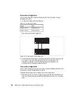
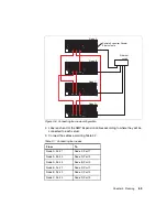
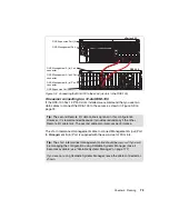
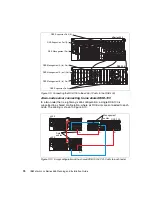
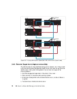
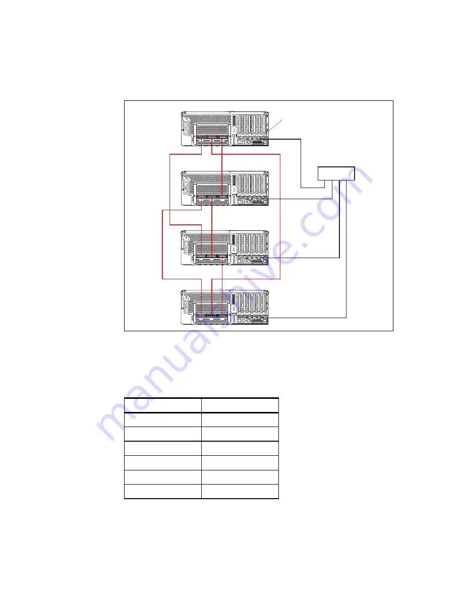
Figure 3-6 Connecting four-node configuration
2. Label each end of the SMP Expansion cables according to where they will be
connected to each server.
3. Connect the cables according Table 3-7.
Table 3-7 Connecting four nodes
From
To
Node A, Port 1
Node C, Port 1
Node A, Port 2
Node D, Port 2
Node A, Port 3
Node B, Port 3
Node B, Port 1
Node D, Port 1
Node B, Port 2
Node C, Port 2
Node C, Port 3
Node D, Port 3
1
2
3
Node A
1
2
3
Node B
1
2
3
Node C
1
2
3
Node D
Ethernet
switch
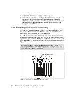
Remote Supervisor Adapter
Ethernet ports
Содержание 88553RX
Страница 2: ......
Страница 214: ...200 IBM Eserver xSeries 455 Planning and Installation Guide Figure 5 14 Connect to the x455...
Страница 228: ...214 IBM Eserver xSeries 455 Planning and Installation Guide...
Страница 229: ...IBM Eserver xSeries 455 Planning and Installation Guide...
Страница 230: ......
Страница 231: ......

